A shell for induction logging tool and its design method

An induction logging and casing technology, applied in chemical instruments and methods, earthwork drilling, wellbore/well components, etc., can solve the inconvenience of installation, debugging and maintenance of induction logging instruments, and affect the use of internal coils and related components Life and other issues, to achieve the effect of meeting the requirements of non-magnetic insulation, shortening the length of the instrument, and reducing costs

Active Publication Date: 2015-10-14
BC P INC CHINA NAT PETROLEUM CORP +1
View PDF7 Cites 0 Cited by
  • Summary
  • Abstract
  • Description
  • Claims
  • Application Information

AI Technical Summary

Problems solved by technology

[0004] In the process of realizing the present invention, the inventor found that the prior art has at least the following problems: the ordinary FRP casing needs to be equipped with a pressure balance mechanism, which makes the installation, debugging and maintenance of the induction logging instrument very inconvenient, and the FRP inner coil and Relevant components are subject to oil pressure, which seriously affects the service life of the internal coil and related components

Method used


Image

  • A shell for induction logging tool and its design method
  • A shell for induction logging tool and its design method
  • A shell for induction logging tool and its design method

Examples


Embodiment 1

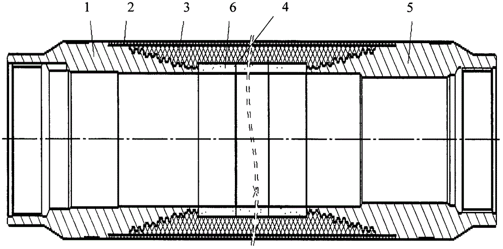
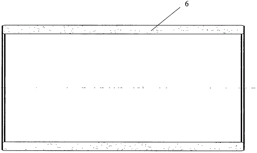
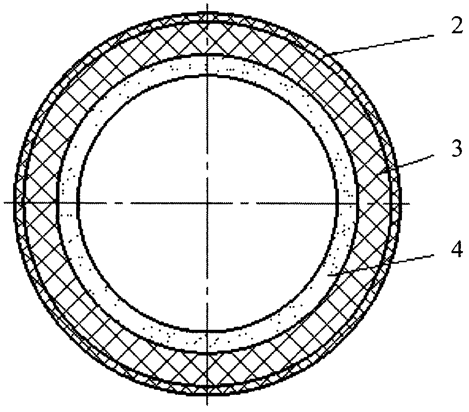
[0025] refer to figure 1 and image 3 , the present embodiment provides a casing for an induction logging tool, including a casing upper joint 1, a ceramic layer 4, a glass fiber reinforced plastic layer 3, a rubber layer 2 and a lower casing joint 5, the upper casing joint 1 and the lower casing joint 5 are both It is a hollow structure, and the ceramic layer 4, the glass fiber reinforced plastic layer 3 and the rubber layer 2 are set in sequence. The ceramic layer 4 is formed by bonding a plurality of ceramic rings 6 of the same specification, and the ceramic layer 4 is bonded to the upper joint 1 of the shell and the lower joint of the shell. 5, and the annular cavity of the ceramic layer 4 communicates with the hollow of the upper shell joint 1 and the shell lower joint 5, the glass fiber reinforced plastic layer 3 is located on the ceramic layer 4, and is connected with the shell lower joint 5 and the shell upper joint 1, and the rubber layer 2 is located on the FRP laye...

Embodiment 2

[0030] refer to figure 2 , the present embodiment provides a casing design scheme for an induction logging tool, which mainly includes the following steps:

[0031] Bond the ceramic ring 6 of the same specification to form the ceramic layer 4, bond one end of the ceramic layer 4 to the upper joint 1 of the shell, bond the other end of the ceramic layer 4 to the lower joint of the shell, and apply the sealant on the ceramic layer 4 The high-performance sealant and the ceramics are fully saturated to realize the insulated connection on the outside and each joint. The ceramic layer 4, the upper joint 1 of the shell and the lower joint 5 of the shell form a matrix, and the upper joint 1 of the shell and the lower joint 5 of the shell are all metal materials , the matrix formed by them and the ceramic layer 4 has a supporting effect on the outer shell layer;

[0032] Wrap FRP on the substrate to form a FRP layer 3, the FRP layer 3 is the middle layer of the casing, and is the mai...


PUM

PropertyMeasurementUnit
thicknessaaaaaaaaaa
thicknessaaaaaaaaaa
thicknessaaaaaaaaaa

Abstract

The invention discloses a shell for sensing a logging device and a design plan for the shell, belonging to the logging inducing field. The shell comprises an upper joint and a lower joint, wherein the upper joint and the lower joint are hollow structures; the shell is characterized by further comprising a ceramic layer, a glass fiber reinforced plastics layer and a rubber layer which are sequentially sleeved; the ceramic layer is formed by bonding ceramic rings with the same specification; the ceramic layer is bounded between the upper joint and the lower joint; the annular empty chamber of the ceramic layer is communicated with the hollow structure; the glass fiber reinforced plastics layer is located above the ceramic layer and is connected with the lower joint and the upper joint; the rubber layer is located on the glass fiber reinforced plastics layer and is connected with the lower joint and the upper joint. The shell for sensing the logging device is simple in structure and convenient to install, debug and maintain the logging sensing device and greatly reduces the device cost.

Description

technical field [0001] The invention relates to the field of induction logging, in particular to a casing for induction logging tools. Background technique [0002] In oil and gas exploration and production, induction logging tools are usually used to obtain formation information. The induction logging tool emits electromagnetic energy, and the emitted energy is induced with the formation to generate an induction signal. The generated induction signal is measured by one or more sensors, and the formation information is obtained through data processing of the detected signal. This instrument is mainly composed of electronic circuit, coil system and instrument shell. When logging, in order to make the coil system of the induction logging tool work normally, the shell of the tool needs to be non-magnetic and insulated, and must be able to have sufficient strength and reliable sealing under the working environment conditions of high temperature 175°C and high pressure 140MPa a...

Claims


Application Information

Patent Timeline
Patent Type & Authority Patents(China)
IPC IPC(8): E21B47/017E21B49/00B32B25/08B32B18/00
Inventor 陈涛汤天知王丽蓉白颜王水航陈章龙宋青山储妮晟贺秋莉
Owner BC P INC CHINA NAT PETROLEUM CORP
Why Eureka
Try Eureka