Automatic transmission shift quality improved via selective use of closed-loop pressure feedback control
A transmission, pressure technology, applied in the direction of transmission control, fluid-driven clutch, non-mechanical drive clutch, etc., can solve the adverse effects of operation changes, unexpected performance and other problems
- Summary
- Abstract
- Description
- Claims
- Application Information
AI Technical Summary
Problems solved by technology
Method used
Image

Examples
Embodiment Construction
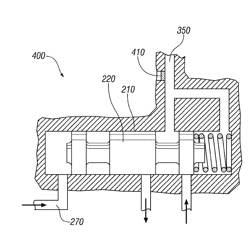
[0050] Referring now to the drawings, in which the figures are shown for the purpose of illustrating certain exemplary embodiments only and not for the purpose of limiting them, figure 1An exemplary clutch control system employing a modulating valve according to the present invention is schematically shown. Clutch control system 200 includes regulator valve 210 , pressure switch 240 , and hydraulic lines 270 , 272 , 274 , 276 , 278 , and 280 . Regulator valve 210 selectively controls the flow of pressurized hydraulic oil to and from hydraulically actuated clutches through movement of a selection mechanism (in the exemplary embodiment, spool valve plunger 220 ) within the regulator valve. The plunger 220 is selectively acted upon by the plunger's first end 222 and the plunger's second end 224, and the balance of forces determines the displacement position of the plunger within the regulator valve. The plunger 220 includes a plunger detail (or plunger detail) 226 (including hol...
PUM
 Abstract
Description
Claims
Application Information
PatSnap Eureka turns technology decisions into work you can execute. Powered by our Innovation Knowledge Graph, it runs expert workflows across engineering, life sciences, materials and intellectual property. Get your review-ready output in minutes.


