Energy-saving servo hydraulic control system for injection machine and control method thereof

A hydraulic control system and control method technology, applied in the field of injection molding machines, can solve the problems of hydraulic control system cost increase, large power consumption, energy waste, etc., and achieve obvious energy saving effects, cost reduction, and precise control effects

Active Publication Date: 2010-01-13
桂林星辰科技股份有限公司
View PDF5 Cites 26 Cited by
  • Summary
  • Abstract
  • Description
  • Claims
  • Application Information

AI Technical Summary

Problems solved by technology

[0006] However, in order to ensure a large working flow, pressure and operating speed of the mechanism, the hydraulic system of this type of injection molding machine needs to be equipped with an oil pump with a large flow rate per unit speed, so the power capacity of the motor and its driver matching the oil pump also needs to be increased.
At present, the current level of ordinary high-power electronic switch modules is difficult to reach the required size. Due to its constraints, the price of high-power servo controllers is relatively high, so the cost of hydraulic control systems increases.
In addition, when the injection molding machine is in the pressure-holding stage, there is little liquid leakage in the hydraulic circuit, and the oil pump only needs to pump out a small flow to maintain the pressure of the hydraulic system; The flow is also greater than the leakage flow of the hydraulic circuit, which will cause the pressure of the hydraulic system to rise and affect the quality of injection molding
In order to avoid excessive pressure in the hydraulic system, it is common practice to install a relief valve on the hydraulic circuit to relieve pressure, resulting in a waste of energy
Even if the influence of the pressure rise in the hydraulic circuit of the injection molding machine is tolerated when the pressure is maintained, the motor is running at a low speed and high torque at this time, and the power consumption is also very large.

Method used


Image

  • Energy-saving servo hydraulic control system for injection machine and control method thereof
  • Energy-saving servo hydraulic control system for injection machine and control method thereof

Examples


Embodiment Construction

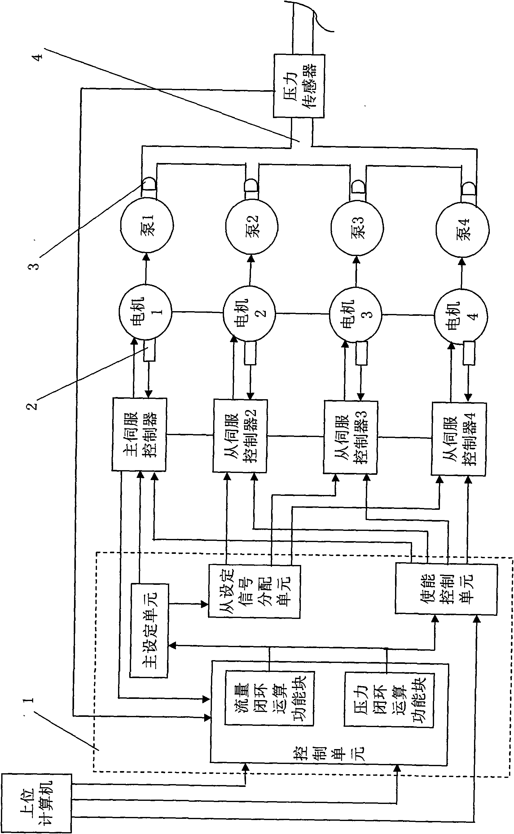
[0038] An example of an energy-saving servo hydraulic control system for an injection molding machine with multiple pumps converging in the present invention figure 1 As shown, it consists of 4 branches; each branch includes a servo controller, a servo motor of the same specification, a speed measuring element 2, an oil pump, and a one-way valve 3; the speed measuring element 2 is installed on each servo motor, and is connected with each servo control Each servo controller, servo motor and speed measuring element 2 form a known speed closed-loop system; each branch servo motor is connected to an oil pump, the oil pump inlet is connected to the oil tank, and each oil pump outlet is equipped with a one-way valve 3, and four oil pumps are one-way The outlet behind the valve 3 is connected to the hydraulic circuit 4 of the injection molding machine; the hydraulic circuit 4 is equipped with a pressure sensor; the No. 1 servo controller is the main servo controller, and No. 2-4 are t...


PUM


Abstract

The invention discloses an energy-saving servo hydraulic control system for an injection machine with multi-pump confluence and a control method thereof. The system comprises N branches, and each branch comprises a servo controller, a servo motor, an oil pump and a check valve, and accesses to an injection machine hydraulic loop in a gathering way. A main control template is connected with a host control computer and each servo controller. Each motor is provided with a speed measurement element which is connected with the servo controller thereof, rotational speed feedback signals of a main servo controller access to a control unit, and the hydraulic loop is provided with a pressure sensor. The control method comprises the following steps: a host computer provides flow and pressure set signals according to an injection molding flow; regulating signals of the flow and the pressure are obtained by the system according to a command of the host computer and the rotational speed and pressure feedback signals to solve the amount of starting motors and the rotational speed of the motors; and a plurality of pumps are controlled to cooperatively work to cause total flow of the hydraulic loop to follow the flow set signals and total pressure of the hydraulic loop to follow the pressure set signals. The invention satisfies the requirements of high-power running and low-power running of equipment, has accurate and agile control, and is obvious to save the energy.

Description

(1) Technical field [0001] The invention relates to the technical field of injection molding machines, in particular to an energy-saving servo hydraulic control system and a control method for an injection molding machine with multi-pump confluence. (2) Background technology [0002] The hydraulic system of the injection molding machine includes the motor and the oil pump driven by it. Controlling the speed of the motor can control the speed of the oil pump, and then control the pressure or flow of the hydraulic circuit to achieve the purpose of controlling the various mechanisms of the injection molding machine. [0003] In the early days, the asynchronous motor was used to directly drive the oil pump, and the hydraulic system of this injection molding machine was difficult to save energy. Finally, a frequency converter is used to control the asynchronous motor. Although there is a certain energy-saving effect, the ordinary asynchronous motor consumes high energy, the respo...

Claims


Application Information

Patent Timeline
Patent Type & Authority Applications(China)
IPC IPC(8): B29C45/76B29C45/82
Inventor 吕虹
Owner 桂林星辰科技股份有限公司
Why Eureka
Try Eureka