
Light guide plate and backlight module

A technology of backlight module and light guide plate, which is applied in the direction of optics, light guide, electric light source, etc., and can solve the problems of poor light source utilization rate of light guide plate, easy generation, and affecting the display quality of liquid crystal display devices, etc.

Active Publication Date: 2015-09-16
AU OPTRONICS CORP
View PDF3 Cites 0 Cited by
  • Summary
  • Abstract
  • Description
  • Claims
  • Application Information

AI Technical Summary

Problems solved by technology

[0005] However, after the light enters the light incident surface of the wedge-shaped light guide plate, it is easy to exit from the inclined surface before being transmitted to the exit area, resulting in poor light source utilization of the light guide plate. In addition, hot spots are also prone to occur. , which affects the display quality of liquid crystal display devices, so how to improve the above problems becomes the improved purpose of the present invention

Method used


Image

  • Light guide plate and backlight module
  • Light guide plate and backlight module
  • Light guide plate and backlight module

Examples


Embodiment Construction

[0081] The detailed description and technical content of the present invention will be described as follows with illustrations, but the accompanying illustrations are for illustration purposes only, and are not intended to limit the present invention.

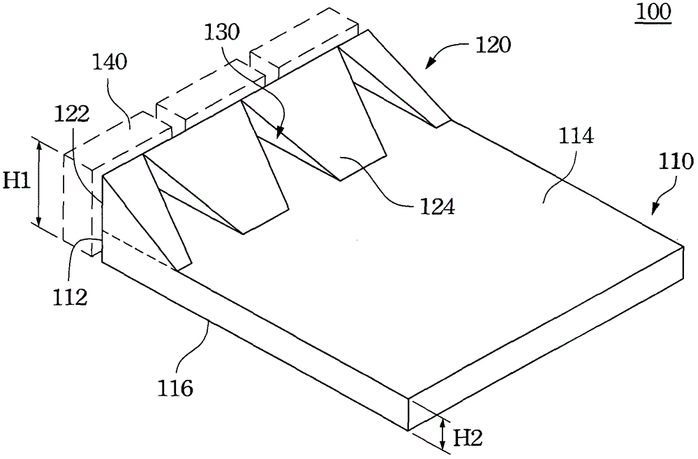
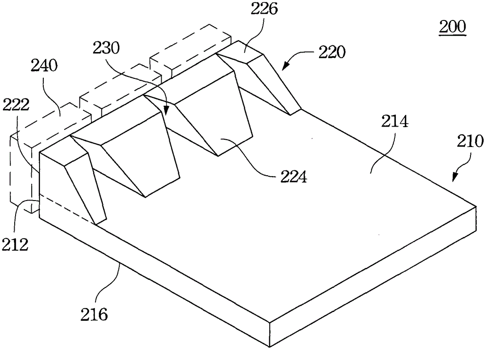
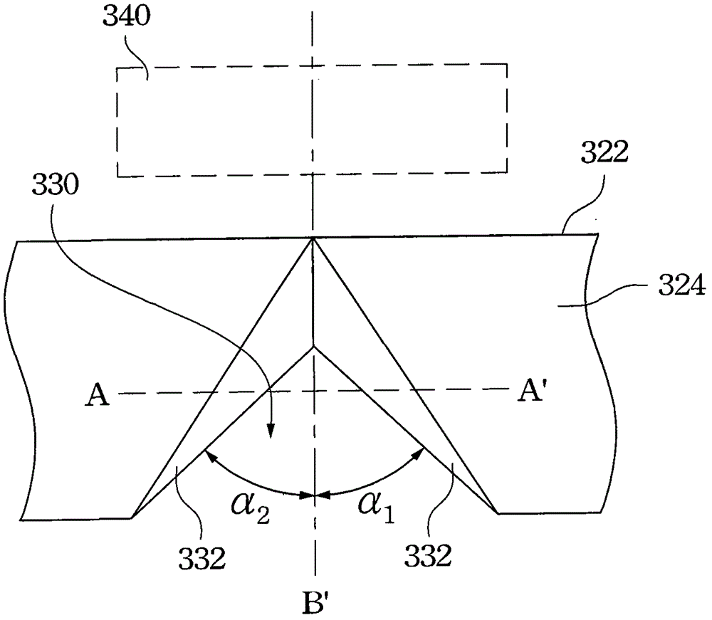
[0082] Please refer to figure 1 , is a three-dimensional schematic view of the first embodiment of the light guide plate of the present invention. The light guide plate 100 includes a light guide body portion 110 and an inclined light guide body 120 , wherein at least one groove 130 is formed between the inclined light guide bodies 120 . First, the light guide body 110 has a first light incident surface 112, a bottom surface 116 and a light exit surface 114. The first light incident surface 112 faces the light source 140 and receives the light emitted by the light source 140. The light source 140 of this embodiment A point light source (light emitting diode) is used as an example for illustration, but it can also be replaced by...


PUM

PropertyMeasurementUnit
heightaaaaaaaaaa
heightaaaaaaaaaa
refractive indexaaaaaaaaaa

Abstract

The present invention discloses a light guide plate and a backlight module, wherein the light guide plate comprises a light guide body portion and an oblique light guide body, the light guide body portion is provided with a first light incidence surface, a bottom surface adjacent to the first light incidence surface, and a light outgoing surface opposite to the bottom surface, the oblique light guide body is located above the light guide body portion and is provided with a second light incidence surface connected with the first light incidence surface, the oblique surface of the oblique light guide body is connected with the light outgoing surface of the light guide body portion, and between the oblique light guide bodies there is provided at least one groove. Furthermore, between the light guide body portion and the oblique light guide body there is provided a wedge-shaped light guide portion.

Description

technical field [0001] The present invention relates to a light guide plate and a backlight module, and in particular to a light guide plate with a groove and an inclined light guide body and a backlight module using the light guide plate. Background technique [0002] Generally speaking, a liquid crystal display device includes a liquid crystal display panel and a backlight module. The liquid crystal display panel is composed of a thin film transistor substrate, a color filter substrate, and a liquid crystal layer arranged on the two substrates. The light source required by the display panel, so that the liquid crystal display device can achieve the display effect. [0003] The light guide plate is an important component in the backlight module. Its main function is to guide the light emitted by point light sources (such as light-emitting diodes) or line light sources (such as cold-cathode tubes) to exit from a plane, and at the same time improve the luminance and luminance...

Claims


Application Information

Patent Timeline
Patent Type & Authority Patents(China)
IPC IPC(8): G02F1/13357F21V8/00F21S8/00F21V13/00
Inventor 张译文范富诚
Owner AU OPTRONICS CORP
Learn More