
Isolation type heat dissipation device of LED (light-emitting diode) lamp

A technology of LED lamps and cooling devices, which is applied in the direction of cooling/heating devices of lighting devices, lighting devices, components of lighting devices, etc., and can solve problems such as light decay, temperature rise of LED lamps, and failure to be effectively solved. To achieve the effect of improving work reliability, ensuring safety performance and reducing temperature

Inactive Publication Date: 2012-07-11
金松山
View PDF3 Cites 11 Cited by
  • Summary
  • Abstract
  • Description
  • Claims
  • Application Information

AI Technical Summary

Problems solved by technology

[0003] However, LED lights have a big heat dissipation problem
The problem of heat dissipation has always been the bottleneck of LED lights in lighting applications, and has not been effectively solved
[0005] The driving power of the existing LED lamps is installed in the radiator, and the insulation and heat insulation structural measures are not taken, which causes the heat of the LED driving power to increase the temperature of the radiator, causing the temperature of the LED lamp to rise and cause serious light decay.

Method used


Image

  • Isolation type heat dissipation device of LED (light-emitting diode) lamp
  • Isolation type heat dissipation device of LED (light-emitting diode) lamp
  • Isolation type heat dissipation device of LED (light-emitting diode) lamp

Examples


Embodiment Construction

[0024] The present invention will be described in further detail below in conjunction with the accompanying drawings.

[0025] In order to overcome a big problem of heat dissipation that has not been effectively solved in the existing LED lamps and the LED drive power supply on the LED lamps is installed in the radiator, the radiator is affected by the heating of electronic components and the safety problem of electrical insulation. The invention provides an isolated heat dissipation device for LED lamps. Reasonable structural measures are adopted for the isolated heat dissipation device for LED lamps, and the problems of electrical insulation and heat insulation are effectively solved.

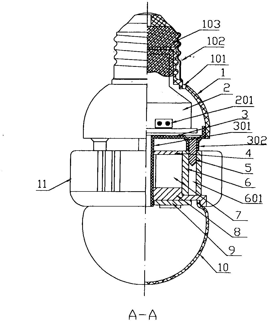
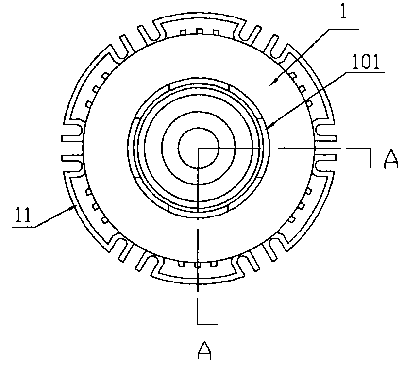
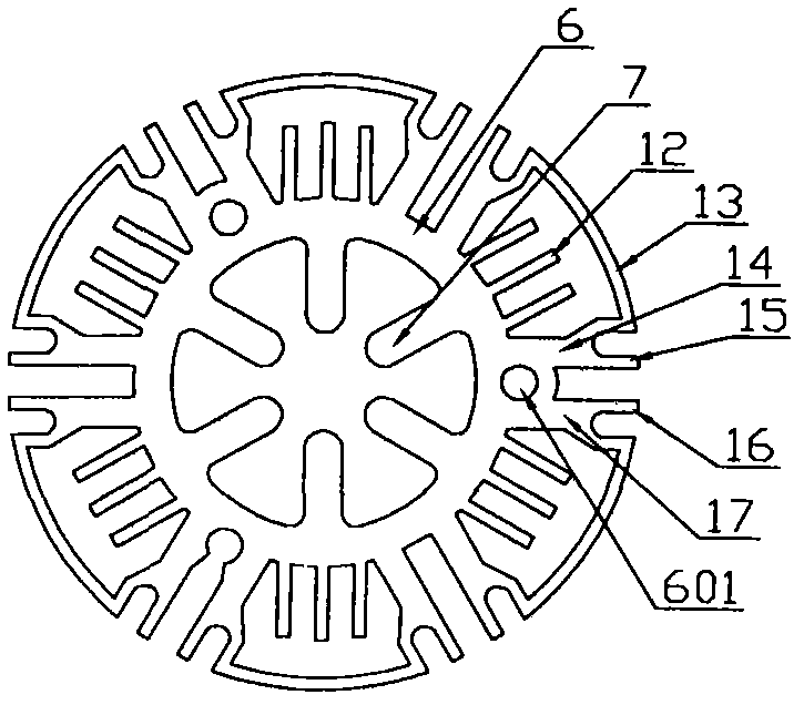
[0026] Depend on Figure 1 to Figure 6 As shown, the present invention includes an insulating lamp holder 1, an LED driver board 2, an isolation base 3, a column type heat sink 11, a heat transfer cylinder 6 and a heat transfer plate 8. When used for semiconductor lighting, the LED aluminum s...


PUM


Abstract

The invention discloses an isolation type heat dissipation device of an LED (light-emitting diode) lamp. The isolation type heat dissipation device comprises an insulating lamp cap, an LED driving plate, an isolating base, heat transfer columns and a heat transfer plate. Heat conducting fins are uniformly distributed on the inner walls of the heat transfer columns, heat conducting strips are arranged on the outer circumferences of the heat transfer columns in sections and are arranged in a one-to-one correspondence manner, corresponding fins and convection covers extend from the tail ends of the heat conducting strips, cooling fins are arranged between one pair of heat conducting strips and another pair of heat conducting strips and are enclosed by the convection covers. The upper surface of the heat transfer plate is connected with the heat conducting fins. The isolation type heat dissipation device has the following advantages: heat on the heat transfer plate is quickly transferred to a pair of heat conducting fins and the cooling fins by the heat transfer columns, and then with the chimney effect of the convection cover, the heat is dissipated into air so as to reduce the temperature rise of the heat transfer plate and an LED aluminium base plate, thereby prolonging the service life of the LED lamp. The isolating base and an insulating lead tube isolate the LED driving plate completely from an external heating part and a conducting metal part, so as to ensure the safety performance of the lamp, reduce the temperature of the LED driving plate, improve the working stability of the LED driving plate, and prolong the service life of electric components, especially the service life of electrolytic capacitors.

Description

technical field [0001] The invention belongs to the technical field of LED lighting, and in particular relates to an isolated heat dissipation device of an LED lamp. Background technique [0002] LED lighting technology is not only energy-saving and environmentally friendly, but also has the characteristics of long life, small size, safety, rich light and color, and easy control. LED lighting is one of the few strategic emerging industries that has gradually mastered key core technologies, has market demand prospects, and has the characteristics of low energy consumption, large driving coefficient, many employment opportunities, and good comprehensive benefits. It not only brings another revolution in lighting sources after incandescent lamps and fluorescent lamps in the history of lighting, but also is an important way to save energy and reduce emissions, and will play a more important role in the development of low-carbon economy. Therefore, various manufacturers are tryi...

Claims


Application Information

Patent Timeline
Patent Type & Authority Applications(China)
IPC IPC(8): F21V29/00F21V17/00F21Y101/02F21V29/71F21V29/74F21Y115/10
Inventor 金松山
Owner 金松山
Learn More