Two-way transmission optical current sensor

A technology of a current sensor and an optical sensor, applied in the field of sensors, can solve the problems such as the optical path structure is not easy to encapsulate the environmental tolerance, and the system performance is adversely affected, and achieves the effect of simplifying the optical path structure, facilitating the packaging, and improving the tolerance.

Inactive Publication Date: 2012-07-11
HARBIN INST OF TECH +1
View PDF5 Cites 9 Cited by
  • Summary
  • Abstract
  • Description
  • Claims
  • Application Information

AI Technical Summary

Problems solved by technology

[0005] The purpose of the present invention is to solve the problem that the optical path structure of the current bulk optical glass type current sensor with one input and two outputs is not eas

Method used


Image

  • Two-way transmission optical current sensor
  • Two-way transmission optical current sensor
  • Two-way transmission optical current sensor

Examples


specific Embodiment approach 1

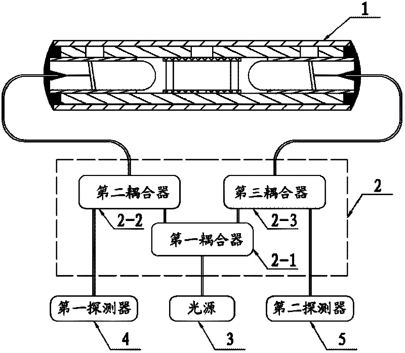
[0015] Specific implementation mode one: combine figure 1 and figure 2 Describe this embodiment mode, the optical current sensor of bidirectional transmission of the present invention is characterized in that it comprises optical sensor 1, coupler module 2, light source 3, first detector 4 and second detector 5; Coupler module 2 comprises the first A coupler 2-1, a second coupler 2-2, a third coupler 2-3; the input end of the first port of the first coupler 2-1 is connected to the output end of the light source 3, and the first coupler 2- The output of the second port of 1 is connected to the input of the second port of the second coupler 2-2, and the output of the third port of the first coupler 2-1 is connected to the second port of the third coupler 2-3 The input end of the first port of the second coupler 2-2 is connected with an input and output end of the optical sensor 1, and the input and output end of the first port of the third coupler 2-3 is connected with the opt...

specific Embodiment approach 2

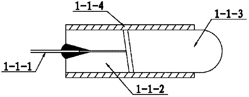
[0018] Specific implementation mode two: combination image 3 Describe this embodiment, the difference between this embodiment and specific embodiment 1 is that its first fiber collimator 1-1 includes a first optical fiber pigtail 1-1-1, a pin 1-1-2, a lens 1- 1-3 and collimator sleeve 1-1-4, the collimator sleeve 1-1-4 is hollow, and the first optical fiber pigtail 1-1-1 is fixed inside the pin 1-1-2 In the hole, the pin 1-1-2 of the first optical fiber pigtail 1-1-1 is adjacent to the lens 1-1-3 and is set and fixed in the collimator sleeve 1-1-4, the pin There is a gap between 1-1-2 and the lens 1-1-3, and the end face of the first optical fiber pigtail 1-1-1 is ground to be inclined to the side wall of the collimator sleeve 1-1-4 by 8 degree angle, and anti-reflection coating is coated on the fiber outlet end face of the first optical fiber pigtail 1-1-1; the connection end of the first optical fiber pigtail 1-1-1 is connected to the first port of the second coupler 2-2 ...

specific Embodiment approach 3

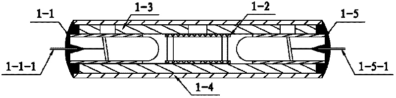
[0022] Specific implementation mode three: combination Figure 4 and Figure 5 This embodiment is described. The difference between this embodiment and the second embodiment is that its magneto-optical glass core 1-2 includes a magneto-optic glass column 1-2-1, a first polarizing glass 1-2-2, a second polarizing glass 1-2-4 and glass core sleeve 1-2-3; first polarizing glass 1-2-2, magneto-optical glass column 1-2-1 and second polarizing glass 1-2-4 from left to right The arrangement set is fixed in the glass core casing 1-2-3, and the polarization directions of the first polarizing glass 1-2-2 and the second polarizing glass 1-2-4 form an included angle of 45 degrees.

[0023] The glass core sleeve 1-2-3 is a hollow glass sleeve, and the inner diameter of the sleeve is slightly larger than the outer diameters of the magneto-optical glass column 1-2-1, the polarizing glass 1-2-2 and the polarizing glass 1-2-4, The magneto-optical glass column 1-2-1, the polarizing glass 1-2-...


PUM


Abstract

A two-way transmission optical current sensor relates to a sensor, for solving the problems of difficult packaging and weak environmental tolerance of one in and two out optical path structure of the prior optical current sensor. The optical current sensor comprises an optical sensor, three couplers, a light source, a first detector and a second detector. The first coupler has a first port connected with an output end of the light source, a second port connected with a second port of the second coupler, and a third port connected with a second port of the third coupler. The second coupler has a first port connected with one input/output end of the optical sensor, and the third coupler has a first port connected with the other input/output end of the optical sensor. The second coupler has a third port connected with an input end of the first detector, and the third coupler has a third port connected with an input end of the second detector. The invention is used for measuring currents, can bidirectionally transmit optical signals, is easy to package, and has strong tolerance to environmental change.

Description

technical field [0001] The invention relates to a sensor, in particular to an optical current sensor for bidirectional transmission. Background technique [0002] The optical current sensor has the advantages of excellent insulation performance, no transient magnetic saturation, large dynamic measurement range, wide frequency response, strong anti-electromagnetic interference ability, small size and light weight, and easy interface with digital equipment. It is especially suitable for high-voltage and high-current applications. Measurement can solve the problems that traditional electromagnetic current transformers are difficult to overcome, so it has a wide application prospect in the power industry. As the power capacity transmitted by the power system increases and the voltage level increases to ultra-high voltage and very high voltage, the optical current sensor shows its unique advantages. [0003] The optical current sensor uses the Faraday magneto-optical effect to m...

Claims


Application Information

Patent Timeline
IPC IPC(8): G01R15/24G01R19/00
Inventor 郭志忠张国庆周颖于文斌申岩路忠峰王贵忠
Owner HARBIN INST OF TECH
Why Eureka
Try Eureka