Novel high voltage optical fiber sensing device
A technology of optical fiber sensing and high voltage, which is applied in the directions of measuring devices, voltage/current isolation, measuring current/voltage, etc. It can solve the problems of complex interference detection devices, lack of verification of long-term stability, and restrictions on popularization and use, etc., to achieve flexible use , Improve the test accuracy and ensure the effect of life
- Summary
- Abstract
- Description
- Claims
- Application Information
AI Technical Summary
Problems solved by technology
Method used
Image

Examples
Embodiment 1
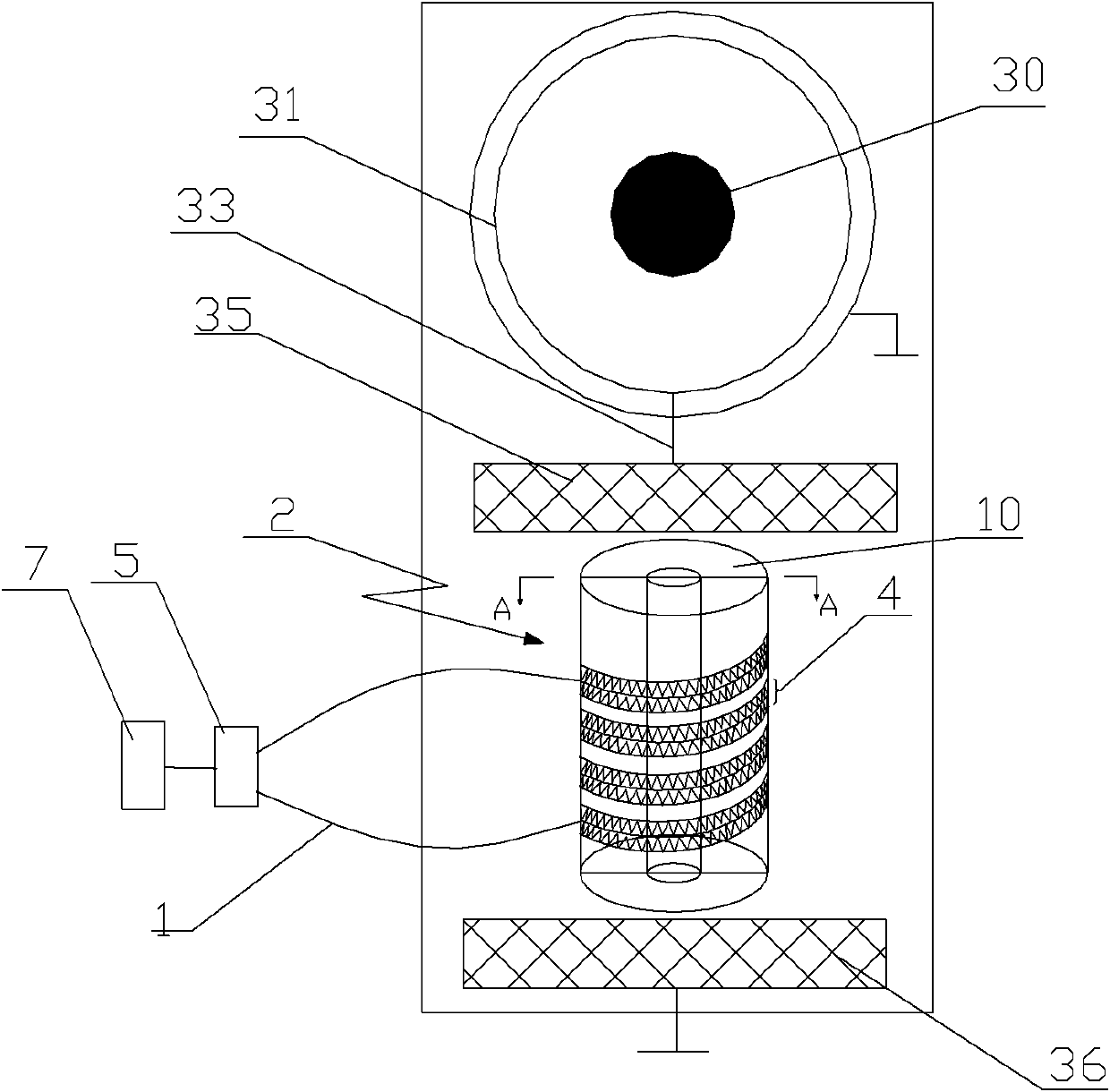
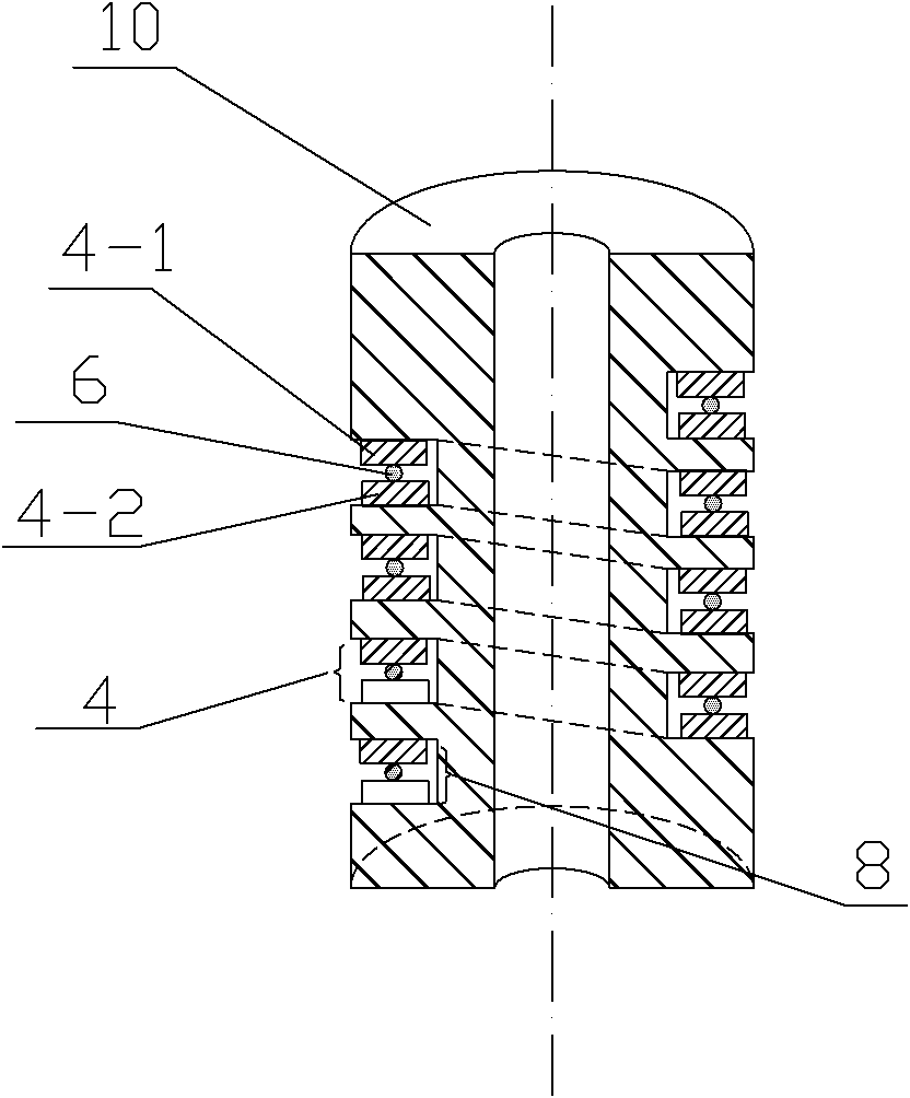
[0034] Such as figure 1 and figure 2 A new type of high-voltage optical fiber sensing device shown includes electrode one 35, ground potential electrode 36 and at least one optical fiber sensitive unit 2 between electrode one 35 and ground potential electrode 36, and the high-voltage bus 30 passes through electrode one 35 and ground potential electrode 36. The ground potential electrode 36 loads the high voltage of the high-voltage bus 30 on the optical fiber sensitive unit 2, and the optical fiber sensitive unit 2 includes a cylinder 10, and at least one curved groove 4 is distributed on the side surface of the cylinder 10 , A-side deformed teeth 4-1 and B-side deformed teeth 4-2 are arranged on opposite surfaces of the groove 4, and the A-side deformed teeth 4-1 and B-side deformed teeth 4-2 correspond to each other alternately , and a signal optical fiber 6 is clamped between the A-side deformed tooth 4-1 and the B-side deformed tooth 4-2, and the A-side deformed tooth 4-...
Embodiment 2
[0046] Such as image 3 As shown, the difference between this embodiment and Embodiment 1 is only that the cylinder 10 selects a crystal material with good temperature performance and inverse piezoelectric performance, wherein the Y axis of the crystal material coincides with the central axis of the cylinder 10, The X-axis of the crystal crystal material is located in a radial direction of the cylinder 10, and the voltage of the electrode 35 and the ground potential electrode 36 is applied to the X-axis direction of the crystal material forming the cylinder 10. When the voltage of the electrode 35 and the ground potential electrode 36 changes, The Y-axis direction of the crystal material deforms and expands, that is, the length of the cylinder 10 made of the crystal material also changes, so that the A-side deformation teeth 4-1 and B on the opposite two surfaces in the groove 4 The distance between the side deformation teeth 4-2 changes, so that the bending curvature of the s...
Embodiment 3
[0048] Such as Figure 4 As shown, the difference between this embodiment and Embodiment 1 is that there are two or more optical fiber sensitive units 2, which are connected in series through a metal tube 37 and installed in an insulating tube 38, the insulating tube 38 is filled with insulating polyurethane 39 in the gap, and corona discharge rings 34 are arranged on both sides of the insulating tube 38, and the voltage of the high-voltage bus 30 is applied to a plurality of optical fiber sensitive units connected in series through electrode one 35 and ground potential electrode 36 2, so that the device can monitor the voltage of the high-voltage bus 30 below 500kv, and the high-voltage bus 30 of a higher voltage level can be monitored by connecting more optical fiber sensitive units 2 in series. The corona discharge ring 34 can reduce the electric field gradient, so that the electric field distribution of the electrostrictive or inverse piezoelectric material included in the...
PUM
 Abstract
Description
Claims
Application Information
 - R&D
- Intellectual Property
- Life Sciences
- Materials
- Tech Scout
- Unparalleled Data Quality
- Higher Quality Content
- 60% Fewer Hallucinations
Browse by: Latest US Patents, China's latest patents, Technical Efficacy Thesaurus, Application Domain, Technology Topic, Popular Technical Reports.
© 2025 PatSnap. All rights reserved.Legal|Privacy policy|Modern Slavery Act Transparency Statement|Sitemap|About US| Contact US: help@patsnap.com