Optical element fixing device and installation method thereof

An optical element and fixing device technology, applied in the optical field, can solve the problems of insufficient manufacturability and assemblability, poor structural stability, insufficient stress elimination, etc., and achieve the effects of simple structure, convenient installation and wide application range

Active Publication Date: 2012-07-11
SHANGHAI MICRO ELECTRONICS EQUIP (GRP) CO LTD
View PDF10 Cites 18 Cited by
  • Summary
  • Abstract
  • Description
  • Claims
  • Application Information

AI Technical Summary

Problems solved by technology

[0005] The purpose of the present invention is to provide an optical element fixing device and its installation method to solve the problems of existing optical e

Method used


Image

  • Optical element fixing device and installation method thereof
  • Optical element fixing device and installation method thereof
  • Optical element fixing device and installation method thereof

Examples


Embodiment Construction

[0035] The optical element fixing device and its installation method proposed by the present invention will be further described in detail below in conjunction with the accompanying drawings and specific embodiments. It should be noted that all the drawings are in very simplified form, and are only used for the purpose of conveniently and clearly assisting in describing the embodiments of the present invention.

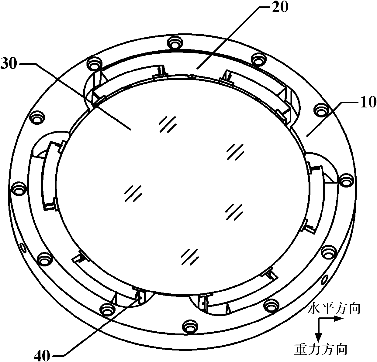
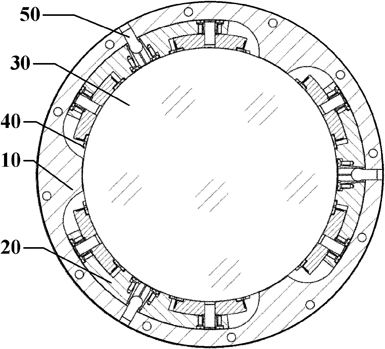
[0036] Such as figure 1 with 2 As shown, the present invention proposes an optical element fixing device, comprising: a mirror base 10, a flexible element 20, and a ball pin 50, wherein the mirror base 10 is a hollow structure matching the optical element 30, and the ball pin 50 connects the mirror base 10 and The flexible element 20 has a cylindrical screw at one end, a ball joint at the other end to connect the flexible element 20, and a shoulder in the middle.

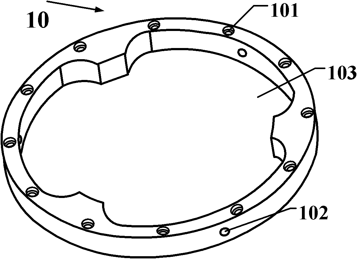
[0037] See image 3 , in this embodiment, the mirror base 10 is a ring structure, and the inner wall ...


PUM


Abstract

The invention provides an optical element fixing device and an installation method thereof. The optical element fixing device comprises a microscope base, flexible elements and ball pins, wherein at least three grooves are formed at equal intervals on the inner wall of the microscope base; the flexible elements are arranged in the grooves in a matching way; and the ball pins are used for connecting the flexible elements with the microscope base. The radial force of the fixing device is controlled by controlling the friction coefficient and transition matching way between the ball pins and corresponding conical sleeves as well as the friction coefficient and transition matching way between a cylindrical pin and a corresponding conical sleeve, so that the influences caused by the thermal deformation and assembly stress deformation of an optical element or optical assembly on the surface type of the optical element are controlled; a flexible element multipoint gluing support structure is adopted, so that the influence of gravity on the surface type is reduced, and release of the thermal stress of an annular optical element in a circumferential direction is realized simultaneously by using the low rigidity characteristics of the flexible elements in a direction which is vertical to the optical axis; and the fixing device provided by the invention has the advantages of simple structure, high stability, convenience for installing, accurate positioning, firm and reliable fixing and wide application range.

Description

technical field [0001] The invention relates to the field of optics, in particular to an optical element fixing device and an installation method thereof. Background technique [0002] With the continuous improvement of lithography resolution requirements, the design requirements for projection imaging objective lenses in the exposure part of advanced lithography equipment are also increasing. High resolution requires the lens to increase the requirements for aberration and system stability in the design. , which not only puts forward higher requirements for the design of the optical system itself, but also greatly increases the difficulty of the structural design of the optical machinery. In the structural design of optical machinery, the stress-free or low-stress fixing technology of optical components can effectively solve the change of the high-resolution lens surface shape, thereby realizing the control of aberrations. For example, in U.S. Patent No. 7,085,080, the len...

Claims


Application Information

Patent Timeline
IPC IPC(8): G02B7/00
Inventor 王洪尊储兆祥彭云平
Owner SHANGHAI MICRO ELECTRONICS EQUIP (GRP) CO LTD
Why Eureka
Try Eureka