
Temperature control circuit in DC-DC (direct current) converter

A DC converter, temperature control circuit technology, applied in temperature control, instrument, non-electric variable control and other directions, can solve the problems of unreliability, damage, thermal runaway, etc., to achieve effective control of shell temperature, reduce output current, output The effect of power reduction

Active Publication Date: 2012-07-11
张家港市华为电子有限公司
View PDF5 Cites 13 Cited by
  • Summary
  • Abstract
  • Description
  • Claims
  • Application Information

AI Technical Summary

Problems solved by technology

[0003] There are two types of DC-DC converters currently on the market: ⑴The product has no temperature protection. This product can be used when the ambient temperature is not high, but once the ambient temperature is too high, the product will be extremely unreliable and easily damaged. Damage or even thermal runaway due to electronic components operating at excessively high temperatures
⑵The product has temperature protection but it is protected by a temperature switch. For example, in summer, the operating temperature of the DC-DC converter in the car may reach above 60°C. When the temperature of the power supply case is as high as 85°C, the power supply has no output, and it needs to wait until the case cools down to 75°C. ℃, which will cause the whole vehicle to be unusable for a long time when the outer casing is cooled to 75 ℃
If the car is parked on the side of the road in a foggy day or at night, if the car cannot turn on the lights, it is very likely to cause an accident and bring serious safety hazards to the travel.

Method used


Image

  • Temperature control circuit in DC-DC (direct current) converter
  • Temperature control circuit in DC-DC (direct current) converter

Examples


Embodiment Construction

[0010] The temperature control circuit used in the DC-DC converter according to the present invention will be further described in detail below with reference to the accompanying drawings.

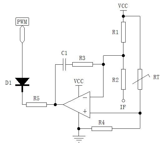
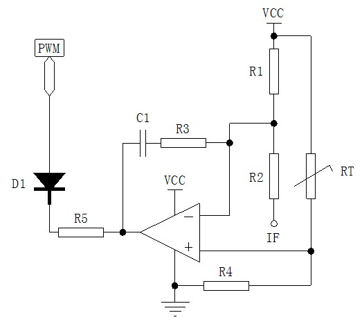
[0011] see figure 1 As shown, the temperature control circuit used in the DC-DC converter of the present invention includes: a thermistor RT used to sense the temperature change of the working environment, and the thermistor RT is connected to the non-inverting input terminal of the operational amplifier and Between the positive pole VCC of the power supply, the inverting input terminal of the operational amplifier is provided with a reference reference voltage, and the reference reference voltage is obtained by dividing the voltage of the second voltage dividing resistor R1 and the third voltage dividing resistor R2 connected in series, and the second voltage dividing resistor R1 and the third voltage dividing resistor R2 are connected between the positive pole VCC of the power supply and...


PUM


Abstract

The invention discloses a temperature control circuit in a DC-DC (direct current) converter. The temperature control circuit comprises a thermistor for sensing the temperature change of the working environment; the thermistor is connected between a non-inverting input end of an operational amplifier and a power anode; reference voltage is set at an inverting input end of the optional amplifier; a capacitor is connected in series with a feedback resistor and then connected between the inverting input end and an output end of the operational amplifier; a first voltage dividing resistor is connected between the non-inverting input end of the operational amplifier and a grounding point; the output end of the operational amplifier is connected with the cathode of a diode through a current limiting resistor; and the anode of the diode outputs a control signal. The temperature control circuit disclosed by the invention has the advantages that: the enclosure temperature can be detected through the thermistor; when the enclosure temperature reaches a set value, the circuit starts working and controls PWM (pulse width modulation) to reduce the duty cycle and achieve the aim of fixing the enclosure temperature by reducing the output current; and thus the circuit can be used for a long time at high temperature.

Description

technical field [0001] The invention relates to a DC-DC converter, in particular to a temperature control circuit used in the DC-DC converter. Background technique [0002] Electric vehicles use the on-board power supply as the power supply system. Generally, the voltage of the power supply battery is as high as several hundred volts, so a DC-DC converter is required to reduce the voltage of several hundred volts to 12V or 24V to power the vehicle's electrical equipment such as CD players and front lights. Lights, rear lights, wipers, etc. power supply. With the rapid development of new energy electric vehicles, the prospect of on-board DC-DC converters is also promising, and the requirements for them are getting higher and higher. [0003] There are two types of DC-DC converters currently on the market: (1) The product has no temperature protection. This product can be used when the ambient temperature is not high, but once the ambient temperature is too high, the product ...

Claims


Application Information

Patent Timeline
Patent Type & Authority Applications(China)
IPC IPC(8): G05D23/24
Inventor 严为人陈伯平
Owner 张家港市华为电子有限公司
Learn More