Laminated structure of radio frequency transformer

A radio frequency transformer, stacking technology, applied in the direction of transformer/inductor coil/winding/connection, etc., can solve the problems of limiting the application of radio frequency transformer, small mutual inductance, large distance between primary and secondary metal coils, etc.

Active Publication Date: 2012-07-11
SHANGHAI HUAHONG GRACE SEMICON MFG CORP
View PDF6 Cites 2 Cited by
  • Summary
  • Abstract
  • Description
  • Claims
  • Application Information

AI Technical Summary

Problems solved by technology

Since the coplanar structure is constrained by the design rules, the distance between the primary and secondary metal coils is large, resul

Method used


Image

  • Laminated structure of radio frequency transformer
  • Laminated structure of radio frequency transformer
  • Laminated structure of radio frequency transformer

Examples


Embodiment Construction

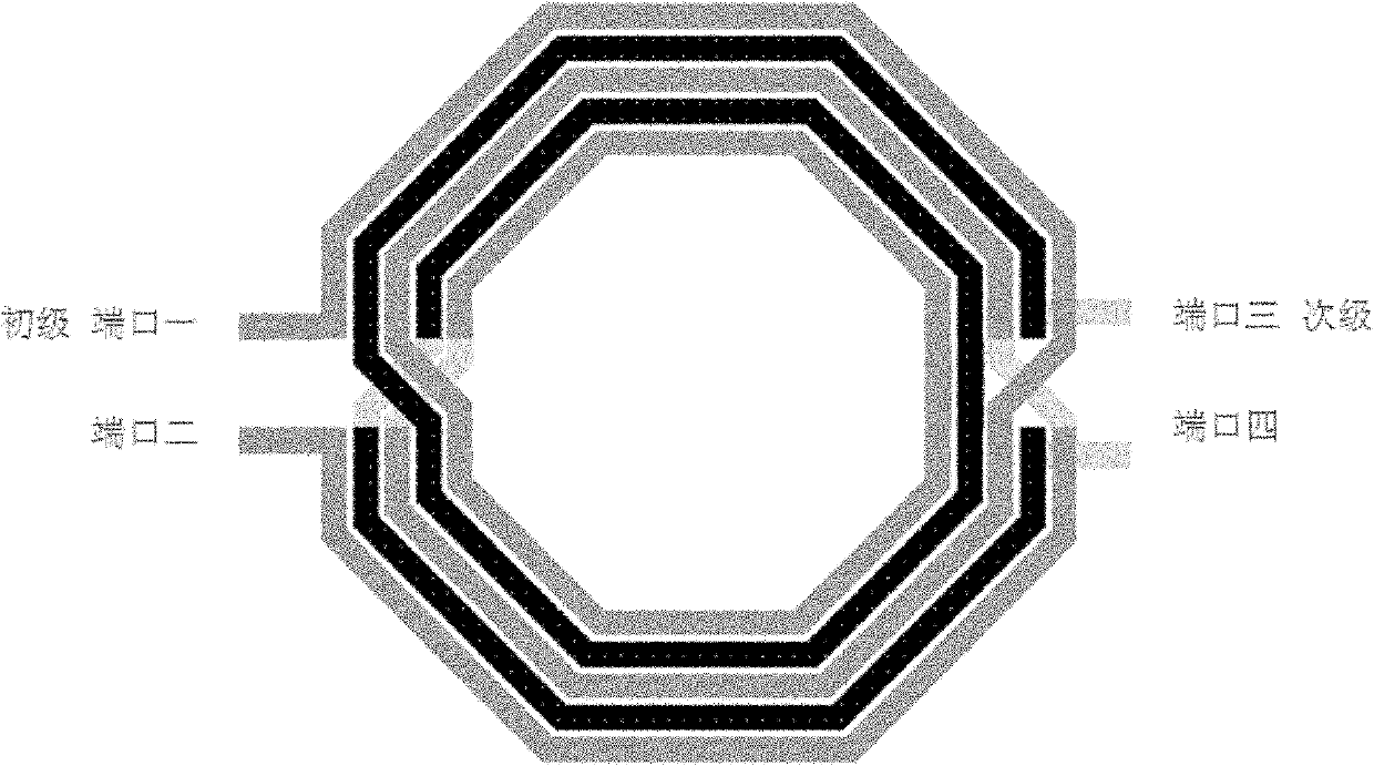
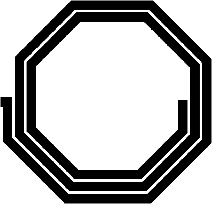
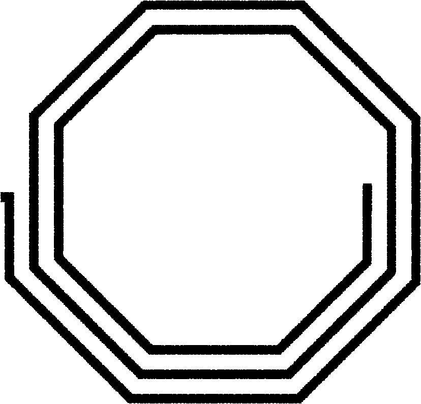
[0022] Now give a preferred embodiment to illustrate the present invention. The laminated radio frequency transformer of the present invention comprises three layers: a metal coil 1 at the top layer, a metal coil 3 at the middle layer and a metal coil 2 at the bottom layer. Such as figure 2 Shown is a schematic diagram of the planar structure of the top metal coil 1 and the bottom metal coil 2, the top metal coil 1 and the bottom metal coil 2 both have coil patterns in the plane, the coil patterns of the two are completely consistent and have the same strip width ws, The top metal coil 1 and the bottom metal coil 2 are used as secondary metal coils for realizing mutual inductance; image 3 Shown is a schematic diagram of the plane structure of the middle layer metal coil 3, which also has a coil pattern in the plane, and the pattern is completely consistent with the top layer metal coil 1, and its strip width is ws1, and ws>ws1, which is used as the primary metal coil for mu...


PUM


Abstract

The invention discloses a laminated structure of a radio frequency transformer, which consists of three metal coil layers which are laminated and include a top metal coil layer, a middle metal coil layer and a bottom metal coil layer. The top metal coil layer is used as secondary metal for realizing mutual inductance, the middle metal coil layer is used as primary metal for realizing mutual inductance, and the bottom metal coil layer is used as secondary metal for realizing mutual inductance. The top metal coil layer, the middle metal coil layer and the bottom metal coil layer are provided with metal coil graphics in a plane, the coil graphics of each metal coil is in set width, the head ends and the tail ends of the top metal coil layer and the bottom metal coil layer are connected with the middle metal coil layer through through-holes among layers or stripped layers, so that parallel connection structure of the metal coils is realized. Since the primary metal coil and secondary metal coil are in laminated structures, restraint of structure design rules in the plane can be avoided, distance between the primary coil and the secondary coil is reduced, coupling between the primary metal coil and the secondary metal coil is improved effectively, and mutual inductance between the primary metal coil and the secondary metal coil is improved as well.

Description

technical field [0001] The invention relates to a laminated radio frequency transformer structure. Background technique [0002] RF transformer is one of the important components in RF CMOS or BiCMOS integrated circuits, and it is widely used in various RF circuit modules such as RF transceivers and voltage-controlled oscillators. [0003] Traditional RF transformers generally adopt a coplanar interwinding structure, such as figure 1 Shown is a schematic diagram of the structure of a traditional planar inter-wound RF transformer. The primary metal coil and the secondary metal coil in the plane have a certain width and a certain distance from each other. It uses the mutual inductance between adjacent metals to realize the signal from the primary to the secondary. transmission. Since the coplanar structure is constrained by design rules, the distance between the primary and secondary metal coils is large, resulting in a small mutual inductance between the primary and seconda...

Claims


Application Information

Patent Timeline
IPC IPC(8): H01F27/28
Inventor 王生荣
Owner SHANGHAI HUAHONG GRACE SEMICON MFG CORP
Why Eureka
Try Eureka