Hybrid relay

A hybrid relay and power supply technology, applied in the direction of relays, circuits, electric switches, etc.

Inactive Publication Date: 2012-07-11
PANASONIC INTELLECTUAL PROPERTY MANAGEMENT CO LTD
View PDF10 Cites 3 Cited by
  • Summary
  • Abstract
  • Description
  • Claims
  • Application Information

AI Technical Summary

Problems solved by technology

Therefore, an inrush current to the load is generated

Method used


Image

  • Hybrid relay
  • Hybrid relay
  • Hybrid relay

Examples


Embodiment approach 1

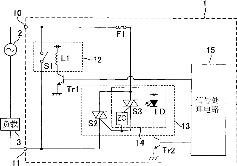
[0036] figure 1 It is a schematic circuit diagram showing the internal configuration of the embodiment.

[0037] Such as figure 1 As shown, the hybrid relay 1 is characterized in that a first power supply circuit formed by a mechanical contact switch 12 is connected in parallel with a second power supply circuit formed by a semiconductor switch 13, and the second power supply circuit is equipped with a temperature fuse F1 to It serves as a safety circuit unit that shuts down the power supply circuit when the temperature of the semiconductor switch 13 is equal to or higher than a predetermined temperature.

[0038] This hybrid relay 1 forms a closed circuit with an AC power source 2 and a load 3 by being connected to terminals 10 and 11 , which are respectively one ends of the AC power source 2 and load 3 connected in series. That is, whether the load 3 is energized or de-energized by the AC power supply 2 is determined by turning the hybrid relay 1 on or off. Here, the AC...

Embodiment approach 2

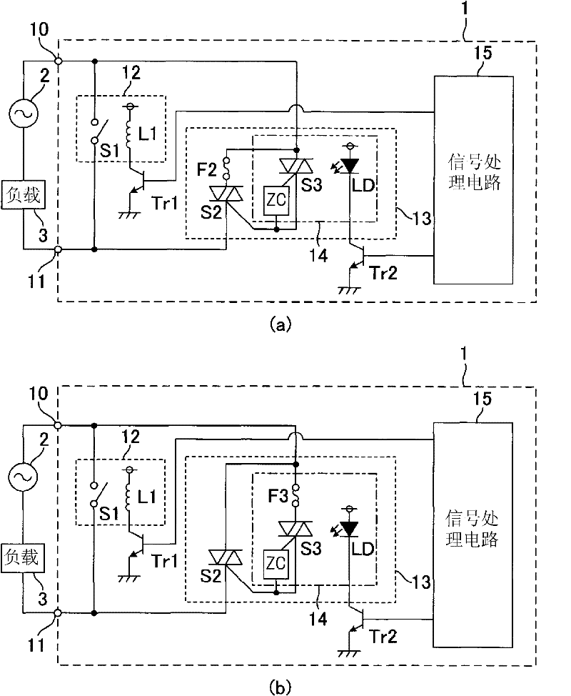
[0049] Next, Embodiment 2 of the present invention will be described with reference to the drawings. image 3 It is a schematic circuit diagram showing the internal structure of the hybrid relay of Embodiment 2. Additionally, for figure 1 The same reference numerals are assigned to the same parts of the hybrid relay according to Embodiment 1 shown, and detailed description thereof will be omitted.

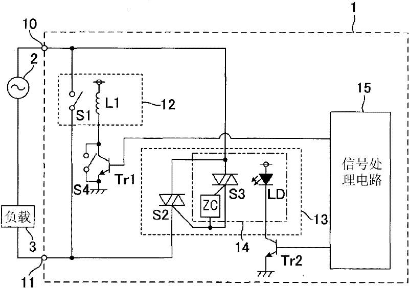
[0050] Such as image 3 As shown, the hybrid relay is structured as follows: from figure 1 In the configuration of Embodiment 1 shown, the thermal fuse F1 is removed, and the thermal switch S4 connected between the emitter and the collector of the transistor Tr1 is provided. Therefore, only in terms of the action performed by the temperature switch S4 is the same as figure 1 The relay switch of the shown embodiment 1 is different, but other structures and actions are the same as figure 1 The embodiment is the same, so its details are omitted. Next, the operation by the te...

Embodiment approach 3

[0055] Next, a hybrid relay according to Embodiment 3 of the present invention will be described. Such as Figure 4 Shown, in this example, is the following structure: figure 1 The hybrid relay of Embodiment 1 shown does not include the thermal fuse F1, but includes a temperature sensor T1 for measuring the temperature of the semiconductor switch and a notification unit 16 for notifying the outside when the temperature of the semiconductor switch 13 is abnormal. Therefore, for figure 1 The same structure of the hybrid relay in the embodiment is assigned the same reference numerals and description thereof will be omitted, and the temperature sensor will be described below.

[0056] The temperature sensor T1 is composed of a temperature sensing element such as a thermistor, and figure 1 Similarly, in order to detect the temperature of the triac S2 among the semiconductor switches 13 , the temperature sensor T1 is fixed on or near the surface of the triac S2 for the tempera...


PUM


Abstract

Provided is a hybrid relay wherein a semiconductor switch can be prevented from reaching a high temperature. The hybrid relay comprises a mechanical contact switch (12) the contact of which is opened/closed by a driving unit, and a semiconductor switch (13) that is connected in parallel with the mechanical contact switch (12). The hybrid relay also has a first power feeding comprising the mechanical contact switch (12) and a second power feeding path comprising the semiconductor switch (13) connected in parallel, as power feeding paths for supplying power to a load from a power supply. The hybrid relay also comprises a thermal fuse (F1), for example, as a safety circuit section for opening the power feeding path when the temperature of the semiconductor switch becomes equal to or more than a prescribed temperature.

Description

technical field [0001] The invention relates to a hybrid relay provided with a mechanical contact switch and a semiconductor switch. Background technique [0002] Conventionally, a hybrid relay having a structure in which a mechanical contact switch and a semiconductor switch are connected in parallel has been used in order to switch between power supply and shutdown for a load equipped with an inverter circuit for inversion control such as lighting fixtures. In addition, a large-capacity smoothing capacitor is attached to a load having an inverter circuit to convert an AC voltage into a DC voltage, and when the load is energized by an AC power source, a large current flows into the smoothing capacitor. Therefore, an inrush current to the load is generated. In particular, when the power supply voltage is high and the load is high, the inrush current flowing into the load increases, and thus a large current based on the inrush current also flows into the hybrid relay connect...

Claims


Application Information

Patent Timeline
Patent Type & Authority Applications(China)
IPC IPC(8): H01H47/00
CPCH01H2047/025H01H47/002H01H9/542H01H47/00
Inventor 住野安弘柴田究大和弘治工藤弘行三浦启中埜进松宫桂
Owner PANASONIC INTELLECTUAL PROPERTY MANAGEMENT CO LTD
Why Eureka
Try Eureka