Base station antenna device embedded with transmission and receiving module

A technology for transceiver modules and base station antennas, applied in antennas, antenna components, radio transmission systems, etc., can solve problems such as increased installation costs, RF signal noise, and reduced transmission efficiency, reducing installation costs, stabilizing signal transmission, The effect of reducing signal noise

Inactive Publication Date: 2012-07-11
ACE TECH
View PDF4 Cites 10 Cited by
  • Summary
  • Abstract
  • Description
  • Claims
  • Application Information

AI Technical Summary

Problems solved by technology

[0005] However, when the transmission path and reception path of the radio frequency signal are formed inside the base station 1 in this way, since the high power amplifier 4 used to form the transmission path and amplify the transmitted radio frequency signal is included in the transceiver unit 3 inside the base station 1, a Connecting the above-mentioned base station antenna device 10 and the cable 2 of the above-mentioned base station 1 to each other causes a problem of lowering the transmission efficiency, and since the high-power amplifier 4 requiring high power should be used in order to improve the transmission efficiency, it is suitable to use the above-mentioned high-power amplifier. 4. The high-power output cables, so there is a problem that the cost of setting them up increases
[0006] Not only that, but at the same time, since the low-noise amplifying section 5 that forms the receiving path and is used to amplify the received radio frequency signal is included in the transmitting and receiving section 3 inside the base station 1, a problem occurs due to mutual connection between the above-mentioned base station antenna device 10 and the above-mentioned base station. Cable 2 of 3 leads to the problem of signal noise in the received RF signal above

Method used


Image

  • Base station antenna device embedded with transmission and receiving module
  • Base station antenna device embedded with transmission and receiving module
  • Base station antenna device embedded with transmission and receiving module

Examples


Embodiment Construction

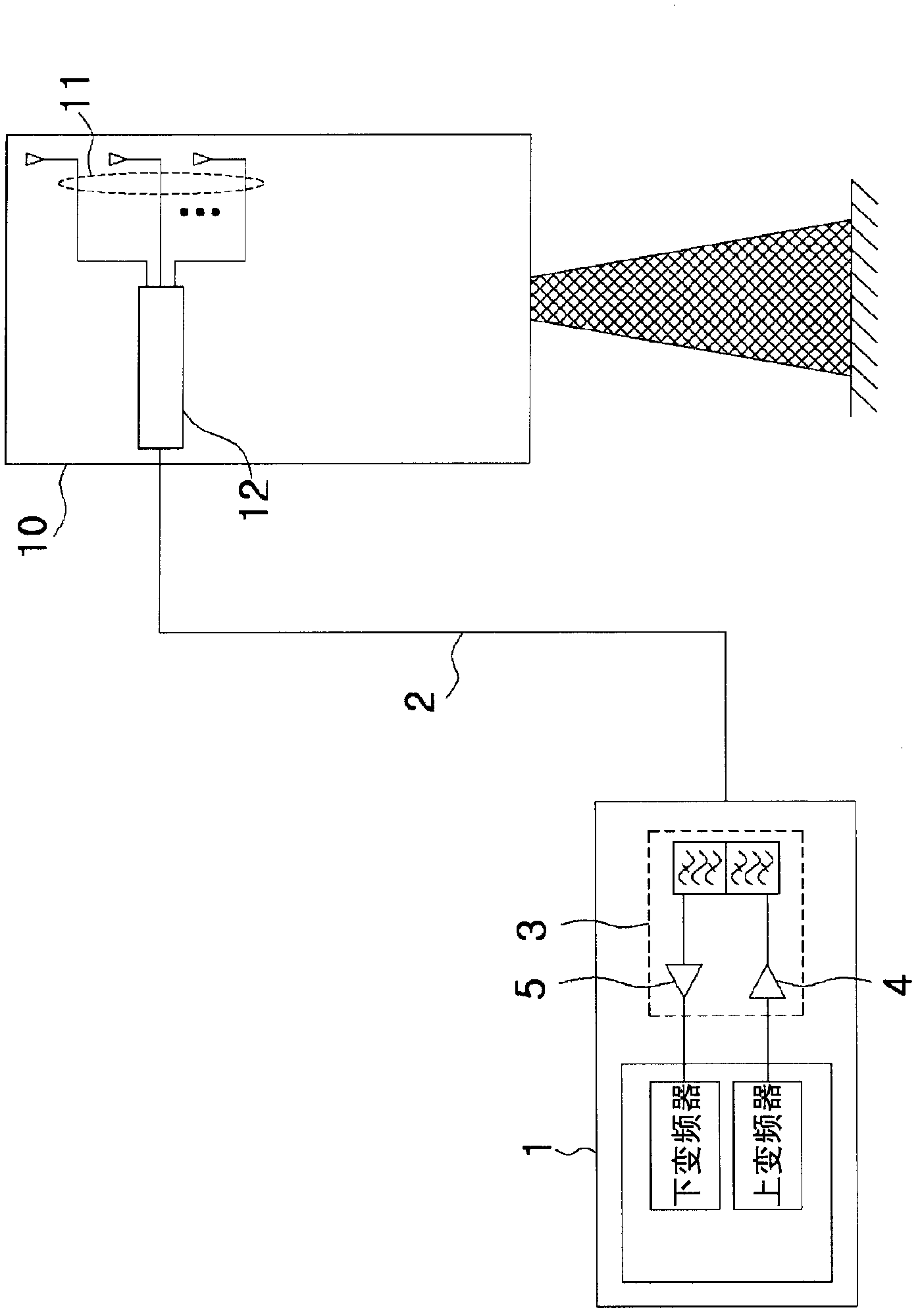
[0027] The base station antenna device 100, 200 with a built-in transceiver module according to the present invention transmits the signal transmitted from the base station 101, 201 to the free space or transmits the signal received from the free space to the base station 101, 201.

[0028] Hereinafter, a preferred embodiment according to the present invention will be described in detail with reference to the accompanying drawings.

[0029] figure 2 It is a schematic configuration diagram showing a base station antenna device that is connected to a base station by an RF cable and has a built-in transceiver module according to an embodiment of the present invention.

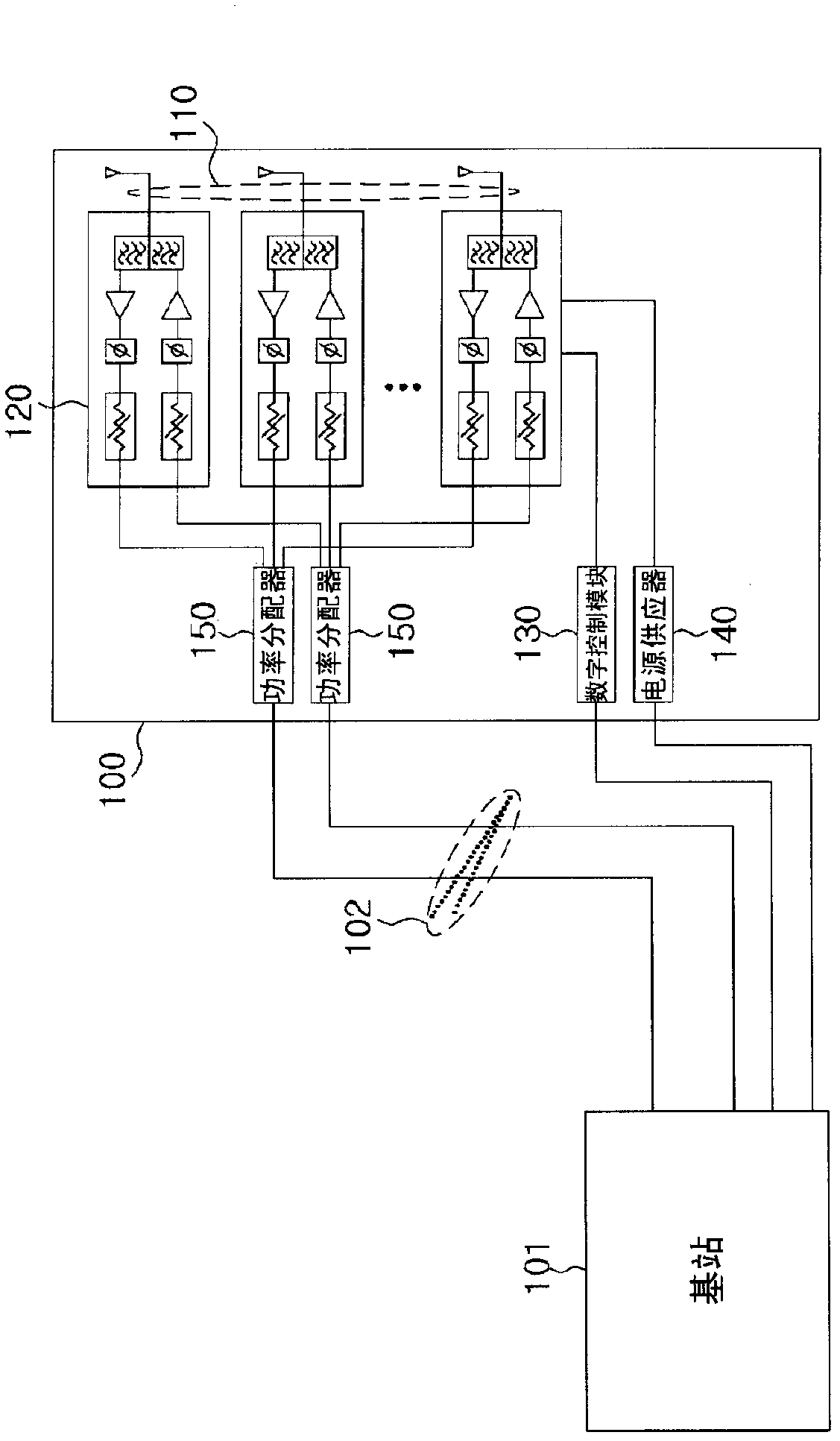
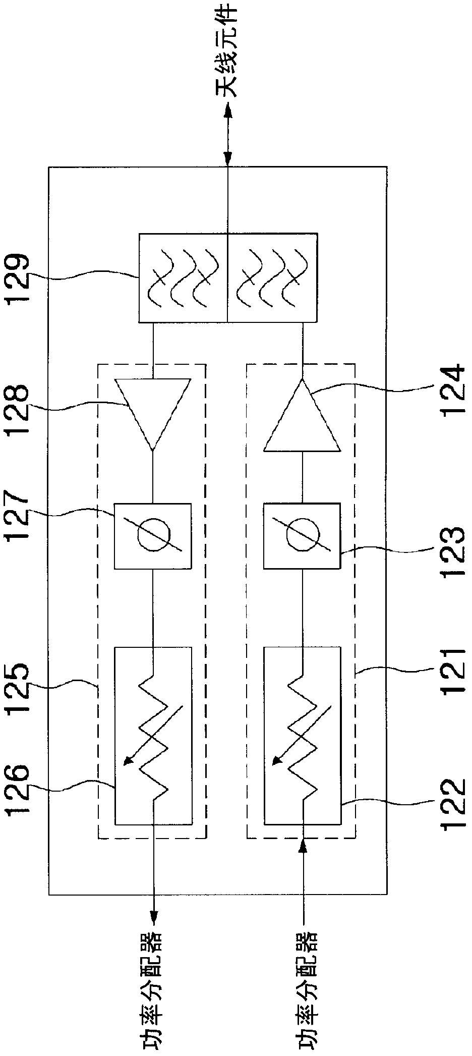
[0030] Such as figure 2 As shown, the base station antenna device 100 with a built-in transceiver module according to an embodiment of the present invention includes: more than one antenna element 110 for transmitting and receiving radio frequency signals; a transceiver module 120 connected to the above antenna...


PUM


Abstract

The present invention relates to a base station antenna device embedded with a transmission and receiving module, comprising: at least one antenna element which transmits and receives an RF signal; the transmission and receiving module which is connected to the antenna element, and forms a transmission path and a receiving path for the RF signal; a digital control module which transmits a digital control signal to the transmission and receiving module, and digitally controls the RF signal that is transmitted and received by the antenna element; and a power supply which supplies the operating power to the transmission and receiving module and the digital control module.; According to the present invention, a digital phase controller and a digital attenuator are equipped inside the transmission and receiving module in order to perform the electronic beam control, and the transmission and receiving module is embedded by being integrated into the antenna element, thereby reducing power loss and the noise of signals while improving the antennas characteristic.

Description

technical field [0001] The invention relates to a base station antenna device with a built-in transceiver module. In more detail, it relates to a base station antenna device with a built-in transceiver module as follows: a digital phase adjuster and a digital attenuator are provided inside the transceiver module forming a transmission path and a reception path of a radio frequency (RF) signal, so as to be able to continuously rotate The beam is controlled electronically, and the above-mentioned transceiver module is built into the antenna element in an integrated manner, thereby reducing power loss, reducing noise, and improving antenna characteristics. Background technique [0002] figure 1 It is a schematic configuration diagram showing a conventional base station antenna device 10 . [0003] Such as figure 1 As shown, the existing base station antenna device 10 is composed of more than one antenna element 11 for transmitting and receiving radio frequency signals and a ...

Claims


Application Information

Patent Timeline
Patent Type & Authority Applications(China)
IPC IPC(8): H04B7/155H01Q3/24
CPCH01Q1/246H01Q3/26H04B7/155
Inventor 徐仁钟曹寅豪吴正根李龙熙李天熙
Owner ACE TECH
Why Eureka
Try Eureka