Adjustable bending sheath tube

A sheath tube and bend-adjusting technology, applied in the field of medical sheath tube, can solve the problems of difficult distal angle of tube body, uneven force, long straight handle, etc., to improve convenience and accuracy, suitable for grasping operation, The effect of shortening the length of the handle

Active Publication Date: 2012-07-18
ZHONGSHAN HOSPITAL FUDAN UNIV +1
View PDF7 Cites 33 Cited by
  • Summary
  • Abstract
  • Description
  • Claims
  • Application Information

AI Technical Summary

Problems solved by technology

Although the position of the button on the handle can indicate the bending angle of the distal end of the sheath, the button is located on one side of the handle. Once the handle is turned to the side that hinders the operator's sight, it is not convenient to judge the bending angle of the distal end of the sheath by observing the handle. It can only be judged by turning on the X-ray fluoroscopy. At this time, it is not convenient for the operator's fingers to control the moving distance of the button.
[0014] In addition, in the prior art, the adjustable curved sheath tube with a lever-type handle reduces the hand tension and contributes to the stability of the operation, but it is difficult to accurately control the angle of the distal end of the tube body, and a preliminary judgment cannot be made by observing the handle. The bending angle of the distal end of the sheath will prolong the X-ray irradiation time
[0015] Through the above analysis, it can be seen that the force of the adjustable curved sheath in the prior art is uneven when adjusting the angle, and the continuity and accuracy are not good; the bending operation is inconvenient, and it is not conducive to observing and calibrating the bending parts of the handle; Straight handles are too long for adjustable curved sheaths with straight handles and are not suitable for delivery of shorter instruments

Method used


Image

  • Adjustable bending sheath tube
  • Adjustable bending sheath tube
  • Adjustable bending sheath tube

Examples


Embodiment Construction

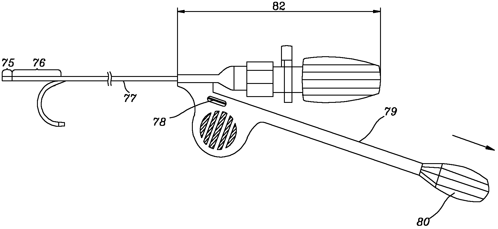
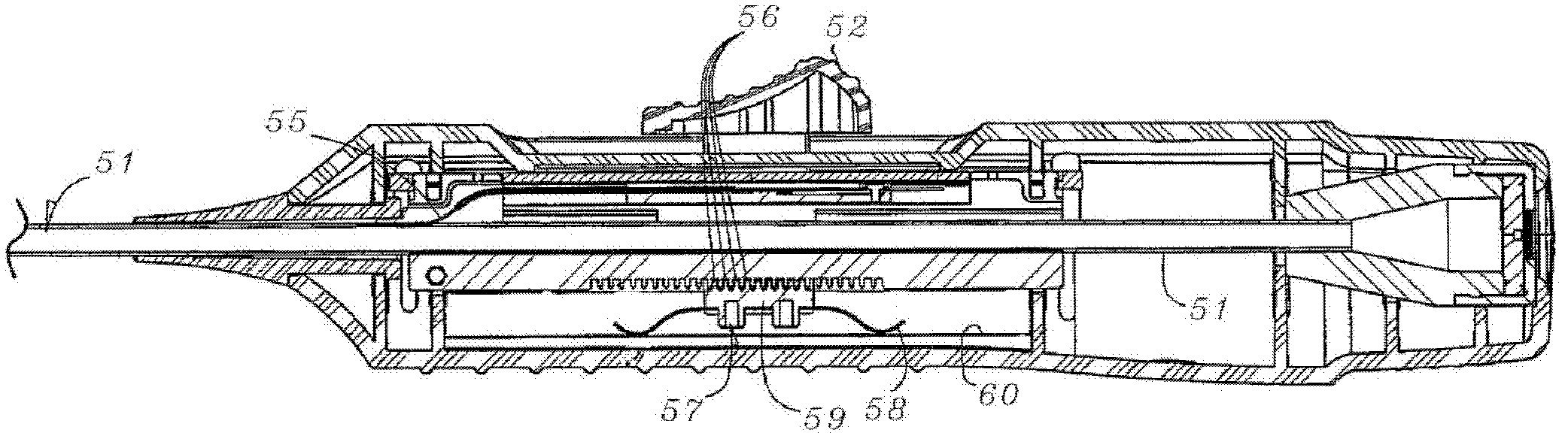
[0047] The solution of the embodiment of the present invention is mainly: the handle of the adjustable sheath adopts a bifurcated structure, and a movable part having a threaded connection with the branch is arranged on the branch of the handle, which can minimize the effective length of the handle (along the length of the handle). The longitudinal length of the tube body), and can improve the accuracy of controlling the bending angle of the distal end of the sheath tube, and the operation process is convenient and easy to control through the self-locking function.

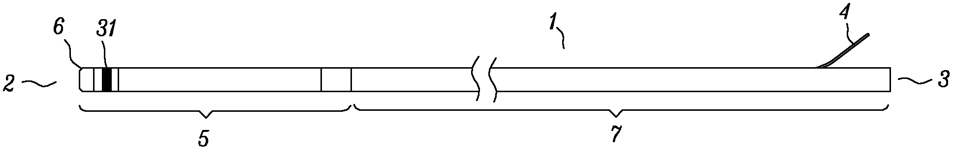
[0048] An adjustable sheath tube proposed by the present invention includes a tube body, a traction wire and a handle. The tube body has a proximal end and a distal end. The proximal end of the tube body is connected with the handle. On one side, the tube body is provided with a filament cavity for threading the traction wire, the branch is provided with a movable member that can be translated along the branch, the...


PUM


Abstract

The invention discloses an adjustable bending sheath tube, which comprises a tube body, a traction fiber and a handle. The traction fiber can slide in the tube body and the handle, the tube body has a near end and a far end, the near end is connected with the handle, the handle comprises a branch which is arranged on one side near the near end of the tube body, a movable part which can transversely move along the branch is mounted on the branch, a near end of the traction fiber is fixed on the movable part, a far end of the traction fiber is fixed on the far end of the tube body, an elastic section is positioned near the far end of the tube body, the bending angle of the elastic section is changed when the movable part moves transversely on the branch, and the movable part is threaded with the branch. Compared with bending sheath tubes in prior art, the bending sheath tube is capable of shortening the effective lengthen of the handle and improving the accuracy of the angle controlling, and the operating process is enabled to be convenient and easy to control.

Description

technical field [0001] The invention relates to the technical field of medical sheaths, in particular to a distally adjustable sheath, which is used in minimally invasive interventional diagnosis and treatment operations on the human body to establish channels to import or export medical instruments, medicines or body fluids. Background technique [0002] At present, interventional diagnosis and treatment sheaths have been widely used in human interventional diagnosis and treatment operations. Usually, various interventional diagnosis and treatment sheaths of different structures, shapes and sizes are needed to establish a channel between the patient's diseased part and the external operation end, so as to introduce various interventional diagnosis and treatment sheaths. Various diagnosis and treatment instruments, medicines or implanted instruments are applied to the diseased part of the patient, or the body fluid of the diseased part can be exported, so as to achieve the pu...

Claims


Application Information

Patent Timeline
Patent Type & Authority Applications(China)
IPC IPC(8): A61M25/01A61M31/00
CPCA61M25/01A61M25/0108A61M25/0136A61M25/00A61M25/0147
Inventor 张庭超陈奕龙符伟国
Owner ZHONGSHAN HOSPITAL FUDAN UNIV
Why Eureka
Try Eureka