

Cooling system for vehicle
A cooling system and vehicle technology, applied in liquid cooling, engine cooling, heating/cooling equipment, etc., can solve the problems of small waste heat, shortage of heat sources, low fuel efficiency, etc., and achieve the effect of improving heating characteristics
- Summary
- Abstract
- Description
- Claims
- Application Information
AI Technical Summary
Problems solved by technology
Method used
Image

Examples
no. 1 example
[0023] In the first embodiment, the cooling system is applied to a hybrid vehicle that obtains drive power from an internal combustion engine and an electric motor.
[0024] Specifically, a hybrid vehicle has a water-cooled engine and an electric motor, and driving force is transmitted to drive wheels of the vehicle through a transmission. The electric motor receives electric power from a secondary battery (secondary battery) through an inverter. The inverter converts the DC voltage to AC voltage and changes the frequency of the AC voltage so that the speed of the motor is controlled.
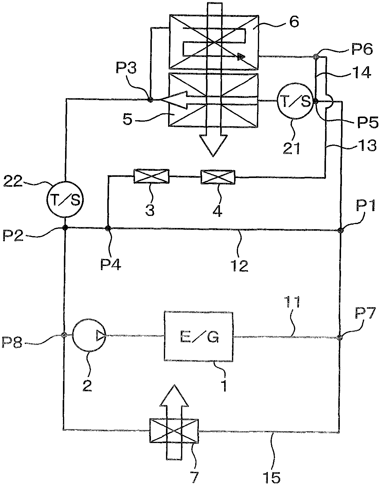
[0025] The cooling system is configured to cool the engine 1, motor generator ( figure 1 not shown in ) and inverter ( figure 1 not shown). The engine 1 corresponds to an energy generator or power source for driving the vehicle. The motor generator corresponds to the electric motor. The cooling water corresponds to the heating medium. A motor generator and an inverter are examples of elec...
no. 2 example
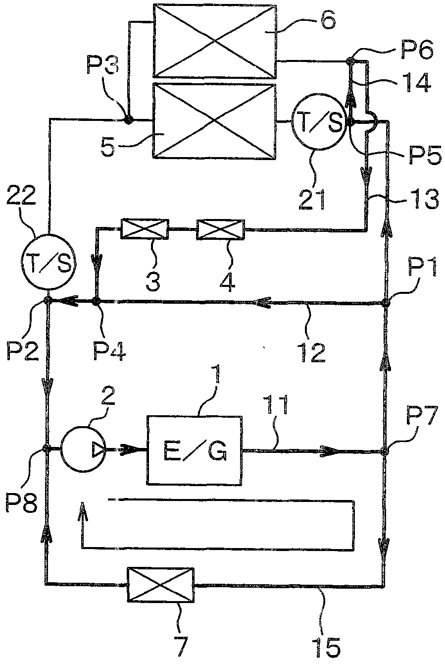
[0095] In the second embodiment, as image 3 As shown, an electric three-way valve 31 is used instead of the first thermostat 21 of the first embodiment. The three-way valve 31 is arranged at the branching point P5 of the circulation channel 11 and is controlled by the control device 32 . The temperature sensor 33 is connected to the inlet side of the control device 32 and is located downstream of the engine 1 and upstream of the first radiator 5 in the circulation passage 11 . The sensor 33 detects the temperature of cooling water discharged from the engine 1 .
[0096] The control device 32 controls the three-way valve 31 based on the signal output from the sensor 33 . Specifically, when the temperature of the cooling water detected by the sensor 33 does not reach the predetermined temperature (about 50-70° C.) required for heating the passenger compartment, the channel 11 between the branch point P5 and the first radiator 5 is closed, and Bypass channel 14 is open. When...
no. 3 example
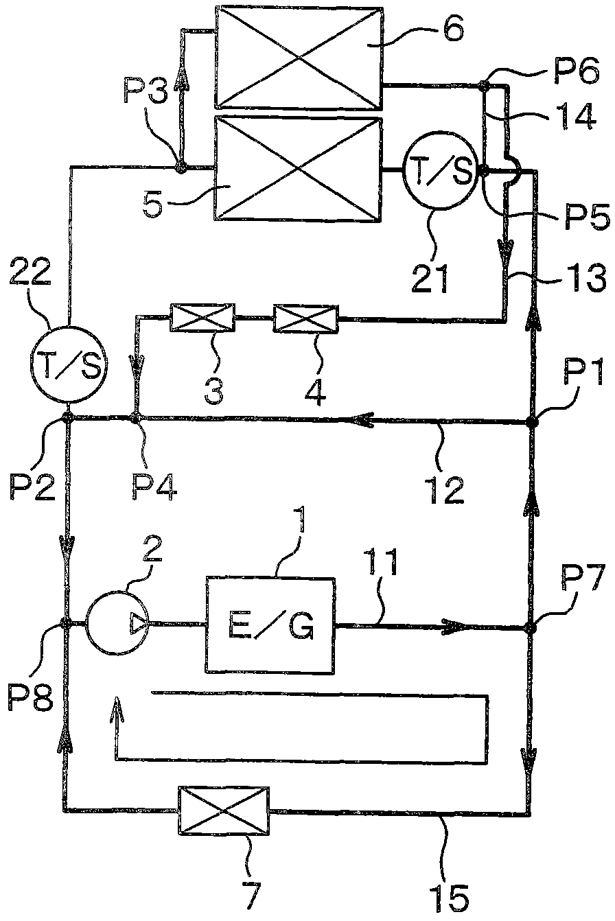
[0100] In the third embodiment, such as Figure 4 As shown, two solenoid valves 35 , 36 are used instead of the electric three-way valve 31 of the second embodiment.
[0101] The first solenoid valve 35 is arranged between the branch point P5 of the circulation passage 11 and the first radiator 5 . The second solenoid valve 36 is arranged in the bypass channel 14 . The first solenoid valve 35 and the second solenoid valve 36 are controlled by the control device 32 .
[0102] The control device 32 closes the first valve 35 and opens the second valve 36 when the temperature of the cooling water detected by the sensor 33 does not reach a predetermined temperature (about 50-70° C.) required for heating the passenger compartment. When the temperature of the cooling water detected by the sensor 33 reaches a predetermined temperature required for heating the passenger compartment, the control device 32 opens the first valve 35 and closes the second valve 36 .
[0103] Advantages s...
PUM
 Abstract
Description
Claims
Application Information