Method for the purification of diesel engine exhaust gases

a technology for diesel engines and exhaust gases, applied in exhaust treatment, gas treatment, mechanical equipment, etc., can solve the problems of exhaust gas heat content that is not sufficient to complete the urea-water solution necessary, complete blockage of the exhaust-gas system, and conversion losses in the scr reaction, so as to reduce the asc and reduce the effect of no limitation in the efficiency of nox removal

Active Publication Date: 2017-02-07
DEUTZ AG
View PDF40 Cites 1 Cited by
  • Summary
  • Abstract
  • Description
  • Claims
  • Application Information

AI Technical Summary

Benefits of technology

[0022]It is an objective of the present invention to provide a method for the purification of diesel engine exhaust gases which does not have the above-mentioned drawbacks of today's methods, especially during operation of the internal combustion engine in the low-load range, and which is characterized by improved energy efficiency while concurrently attaining the best possible cost-effectiveness for the entire system.
[0026]c) the exhaust gas resulting from step b) is passed through an SCR catalytically activated particulate filter (SDPF) in order to reduce the particles contained in the exhaust gas as well as the nitrogen oxides contained in the exhaust gas;
[0029]Metering in the urea-water solution (HWL) that has been conditioned, that is to say, preheated to a temperature of 80° C. to 90° C. [176° F. to 194° F.] in the exhaust-gas system, makes it possible, first of all, for the metering in to be carried out at lower exhaust-gas temperatures (180° C. to 200° C. [356° F. to 392° F.]) than in the case of conventional metering methods (200° C. to 230° C. [392° F. to 446° F.]). Secondly, since less thermal energy needs to be fed in to process the urea-water solution into ammonia than is the case with conventional systems, this advantage can be utilized in order to shorten the mixing segment upstream from the SDPF or from the SCR catalytic converter rather than in order to lower the metering threshold temperature.
[0031]Owing to the (partial) integration of volumes of the SCR catalytic converter into the particulate filter, the exhaust-gas after-treatment system can be smaller than in conventional systems. This leads to improved heating characteristics of the exhaust-gas after-treatment system following a cold start and also to considerably lower heat losses via the exhaust-gas system. Moreover, there are also advantages in terms of space. The SCR catalytic converter, which is arranged downstream from the particulate filter in the flow direction of the exhaust gas, is employed selectively, namely, whenever the SCR volume that can be integrated into the particulate filter is not sufficient to ensure an NOx conversion rate >97% in the entire system over the running time (8000 operating hours).
[0035]For purposes of providing sufficient NO2 for the soot burn-off needed for the passive regeneration of the particulate filter, the upstream DOC has to provide more than 50% NO2 in the NOx at operating points up to an exhaust-gas temperature of 350° C. to 375° C. [662° F. to 707° F.]. If the “CRT® reaction” transpires more quickly than the “slow SCR reaction”, the NO2 excess is available for the soot burn-off, thus ensuring a passive regeneration of the particulate filter.
[0041]The limitation of the above-mentioned lower temperature metering threshold falls within the range of the operating temperature window of the SCR catalytic converter. Metering in gaseous ammonia eliminates the risk of crystallization of urea and urea-derived products such as isocyanic acid, cyanuric acid and melamine that can result from the incomplete degradation of urea and that can lead to a complete blockage of the exhaust-gas system if the operating temperatures are too low. With this method, there is likewise no limitation in the NOx removal efficiency due to incomplete processing of the urea to form ammonia. Overdosing the reducing agent in order to compensate for incomplete urea processing at low-load operating points becomes superfluous. It is possible to reduce the ASC and / or to completely avoid the ammonia secondary emission of the (permissible) 10 Vppm on average over time without ASC.

Problems solved by technology

Particularly at low-load operating points, however, the amount of heat contained in the exhaust gas is often not sufficient to completely process the injected urea-water solution necessary for the complete reduction of the nitrogen oxides that are likewise present in the exhaust gas.
This results in deposits (crystallization) of urea and urea-derived products such as isocyanic acid, cyanuric acid and melamine in the exhaust-gas system, which might cause a complete blockage of the exhaust-gas system as well as conversion losses in the SCR reaction due to inadequate provision of the stoichiometric amount of ammonia needed for the nitrogen oxide reduction.

Method used


Image

  • Method for the purification of diesel engine exhaust gases
  • Method for the purification of diesel engine exhaust gases
  • Method for the purification of diesel engine exhaust gases

Examples


Embodiment Construction

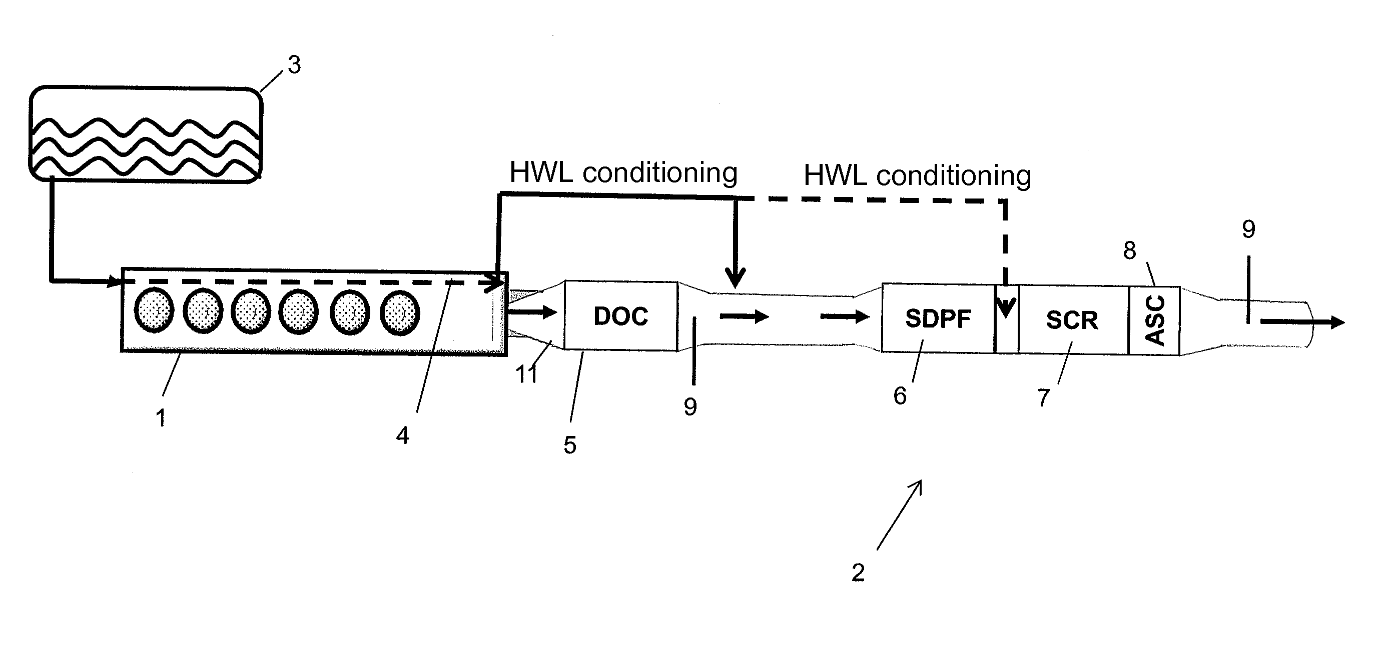
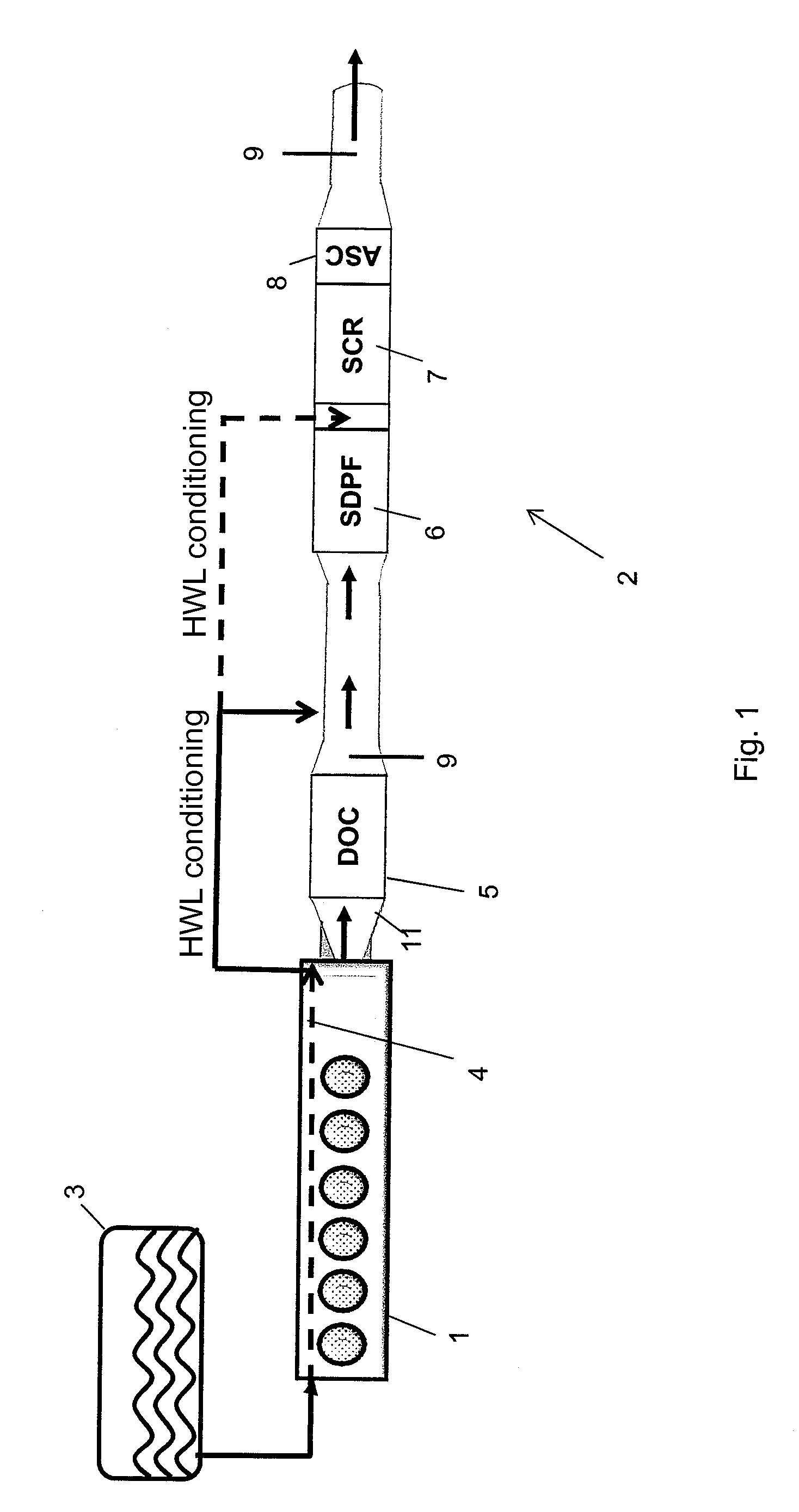
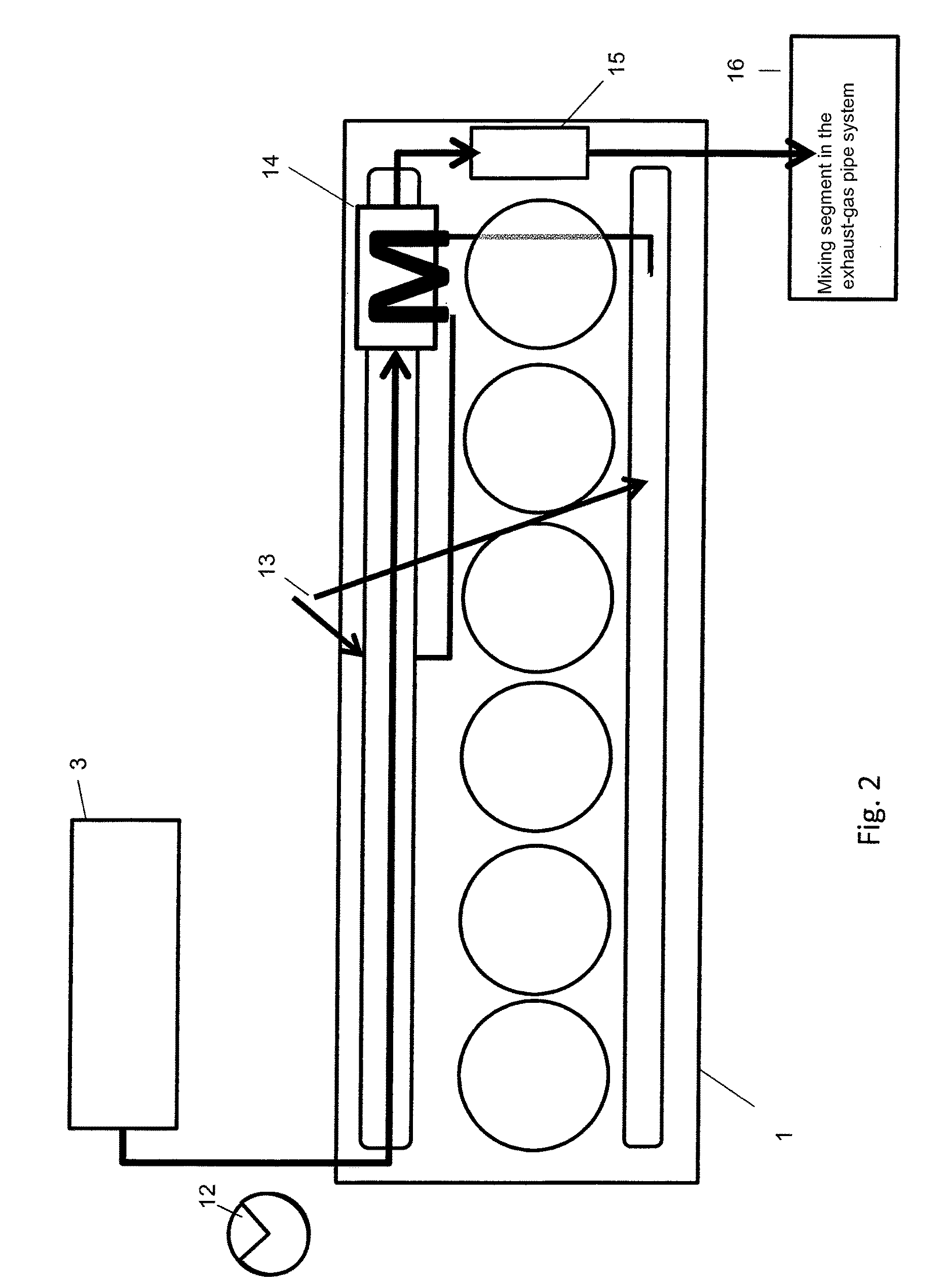
[0045]FIG. 1 shows an internal combustion engine 1 comprising an exhaust-gas line 2 and a urea-water solution tank 3. A NOx sensor 9 and a urea-water solution feed device that is supplied by the urea-water solution heat exchanger 14 (FIG. 2) are arranged in the exhaust-gas line 2 between the DOC 5 and the SDPF 6 in the flow direction of the exhaust gas. The urea-water solution heat exchanger 14 can also supply the urea-water solution feed device with urea-water solution between the SDPF 6 and the SCR 7. An ammonia slip catalyst (ASC) 8 is located downstream from the SCR 7 in the flow direction of the exhaust gas. At the end of the exhaust-gas line 2, there is a NOx sensor 9. In an alternative configuration, it is provided that the urea-water solution heat exchanger 14 is arranged essentially in a double-walled exhaust-gas pipe 11 that has two NOx sensors 9, whereby one NOx sensor 9 is situated between the DOC 5 and the SDPF 6, while the other is behind the ASC 8.

[0046]FIG. 2 shows a...


PUM

PropertyMeasurementUnit
temperatureaaaaaaaaaa

Abstract

A method in which the exhaust gas that is to be purified is passed through an exhaust-gas line containing a diesel oxidation catalyst (DOC) for the oxidation of residual gaseous hydrocarbons (HC) and carbon monoxide (CO) in order to form carbon dioxide (CO2) and for the at least proportional oxidation of the nitrogen monoxide (NO) contained in the exhaust gas in order to form nitrogen dioxide (NO2) is provided.

Description

[0001]This claims the benefit of German Patent Application DE 10 2014 001 880.6, filed Feb. 14, 2014 and hereby incorporated by reference herein.[0002]The invention relates to a method for the purification of diesel engine exhaust gases.[0003]The power per unit of displacement provided by engines of the new generation is continuously increasing. As a result, especially in the application of lower performance levels, ever colder exhaust-gas temperatures occur at which it is no longer possible to ensure the proper operation of a “classic” exhaust-gas after-treatment system having an SCR catalytic converter located at a distance from the engine.[0004]Especially in the low-load range, deposits stemming from the crystallization of urea and urea-derived products can hardly be avoided when a urea-water solution (HWL) that is not temperature-controlled is metered in. Over the course of prolonged operation in the lower partial-load range, the resulting deposits can lead to a blockage of the ...

Claims


Application Information

Patent Timeline
Patent Type & Authority Patents(United States)
IPC IPC(8): F01N3/035B01D53/94F01N3/28F01N3/20
CPCB01D53/9477B01D2255/904B01D53/90B01D53/9413B01D53/9436B01D53/944F01N3/106F01N3/208F01N3/035B01D2251/2067B01D2255/9155B01D2258/012F01N2610/02F01N2610/10F01N3/103F01N13/009Y02A50/20Y02T10/12B01D53/9459F01N3/023F01N9/00
Inventor WITTROCK, MEIKEKLEIN, ULFLEYH, GERALD
Owner DEUTZ AG
Why Eureka
Try Eureka