
Efficient laminated sludge dehydrator

A sludge dewatering machine and lamination technology, which is applied in the direction of dewatering/drying/concentrating sludge treatment, etc., can solve the problems of low treatment efficiency, increase water intake, balance and efficient workload, and improve work efficiency and energy. The effect of utilization

Active Publication Date: 2012-07-18
JIANGSU ZHAOSHENG ENVIRONMENTAL PROTECTION TECH CO LTD
View PDF3 Cites 4 Cited by
  • Summary
  • Abstract
  • Description
  • Claims
  • Application Information

AI Technical Summary

Problems solved by technology

[0003] Aiming at the shortcomings of the above-mentioned existing laminated dewatering machine, the cylinder body of which is of equal diameter and straight cylinder, and thus low treatment efficiency for sewage with high water content, the applicant provides a high-efficiency laminated sludge dewatering machine with reasonable structure, so that it can Effectively improve the treatment efficiency of high water content muddy sewage

Method used


Image

  • Efficient laminated sludge dehydrator
  • Efficient laminated sludge dehydrator

Examples


Embodiment Construction

[0011] The specific implementation manner of the present invention will be described below in conjunction with the accompanying drawings.

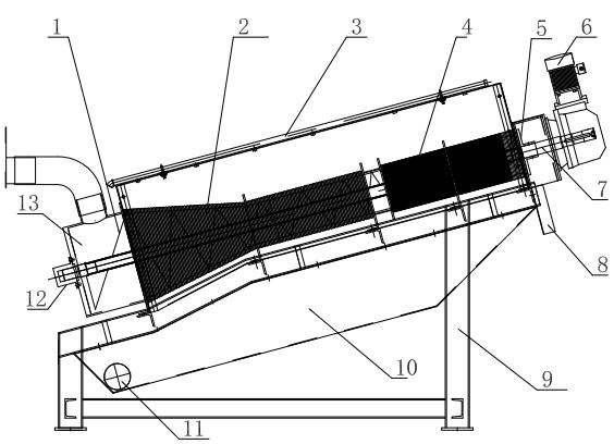
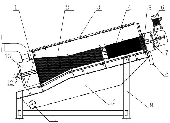
[0012] Such as figure 1 As shown, the basic structure of the high-efficiency laminated sludge dewatering machine described in the present invention is the same as that of the existing laminated sludge dewatering machine. It consists of two sections, the front stage concentration part 2 and the rear stage dehydration part 4. The filter cartridge is installed on the bracket 9 at a certain angle in an oblique upward manner. The water inlet chamber 13 is located at the front end of the concentration part 2. The screw shaft 7 is set on the In the center of the filter cartridge, the auger motor 6 installed at the rear end of the dehydration part 4 is driven to rotate, and the spiral blade 1 continuously pushes the sludge forward, and at the same time, it also continuously drives the swimming ring to clean the filter joints to prevent clogging. ...


PUM


Abstract

The invention discloses an efficient laminated sludge dehydrator. A dynamic and static ring combined filtering cylinder is formed by mutually laminating a fixed ring and a dynamic ring, is divided into a front section of concentrating part and a back section of dehydrating part and is obliquely and upwards arranged on a bracket at certain angle; a spiral shaft is arranged in the center of the filter cylinder and is driven to rotate by an auger motor; spiral blades are arranged at the periphery of the spiral shaft; and the dynamic and static ring combined filtering cylinder is conical, i.e. the front part is thicker than the rear part, the outer diameters and the inner diameters of the fixed ring and the dynamic ring are gradually reduced from the front part water inlet section to the rearpart to form a conical structure with a flare mouth, correspondingly, the outer diameters of the spiral blades also adapt to the inner diameter of the fixed ring and are gradually reduced. Due to theflare mouth, the water inlet amount can be increased in multiples, so relatively more sludge can be conveyed to the rear part to be dehydrated, the workload of the front section and the rear section of the laminated sludge dehydrator is balanced and efficient, the working efficiency of equipment and the utilization rate of energy resources are effectively improved, and the laminated sludge dehydrator is particularly applicable to the treatment on the high-water content sludge-containing sewage.

Description

technical field [0001] The invention relates to the field of sewage treatment equipment, in particular to a high-efficiency laminated sludge dehydrator. Background technique [0002] Laminated sludge dewatering machine (hereinafter referred to as laminated dewatering machine) is generally used to dehydrate sludge with high water content, and is widely used in municipal sewage treatment projects and petrochemical, light industry, chemical fiber, papermaking, pharmaceutical, leather, etc. Water treatment systems in industrial sectors. The laminated main body of the dehydrator is a filter device formed by stacking fixed rings and swimming rings, and the screw shaft runs through it. The front section is the enrichment section, and the rear section is the dehydration section; The filter seams between the moving rings gradually become smaller, and the pitch of the screw device running through the cylinder composed of the fixed ring and the moving ring also gradually becomes small...

Claims


Application Information

Patent Timeline
IPC IPC(8): C02F11/12
Inventor 周震球周建华尹志强柏亚玲尹曙涛
Owner JIANGSU ZHAOSHENG ENVIRONMENTAL PROTECTION TECH CO LTD
Learn More