Novel turbo-type pneumatic submersible pump with multiple nozzles

A pneumatic submersible pump and multi-nozzle technology, applied to non-variable pumps, pumps, pump devices, etc., can solve the problems of poor sewage discharge capacity, high cost, short service life, etc., and achieve strong sand discharge capacity and high energy efficiency. The effect of high rate conversion and long service life

Inactive Publication Date: 2012-07-18
CHANGZHOU COLLEGE OF INFORMATION TECH
View PDF5 Cites 5 Cited by
  • Summary
  • Abstract
  • Description
  • Claims
  • Application Information

AI Technical Summary

Problems solved by technology

The vane pump was used early and widely because of its relatively high flow rate and head, but because of the sliding friction between the vane and the cylinder and between the vane and the guide groove, even if it is equipped with a lubricator, it needs to be repaired after less than ten days of continuous use. ; Although the turbo pump does not have the above problems, it generally has low flow rate and head flow rate, and poor sewage discharge capacity (generally, the diameter of sediment particles is not greater than 5mm); while the gear pump uses a pair of meshing gears as the power source, which requires a very pure gas source. , but also has the problem of tooth surface wear, and the scope of application is small
Although some improved turbopumps have appeared at present, they are either complicated in structure and high in cost, or the improvement effect is not obvious, and their service life is short, and most of the turbines are welded by base body, blades, and shrouds, so it is difficult to guarantee their manufacturing accuracy. Affects the conversion efficiency of wind energy to kinetic energy

Method used


Image

  • Novel turbo-type pneumatic submersible pump with multiple nozzles
  • Novel turbo-type pneumatic submersible pump with multiple nozzles
  • Novel turbo-type pneumatic submersible pump with multiple nozzles

Examples


Embodiment Construction

[0016] The present invention will be further described below in conjunction with the accompanying drawings and specific embodiments.

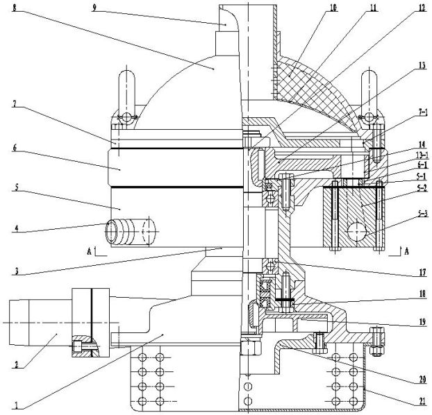
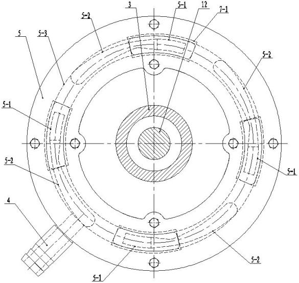
[0017] Such as Figure 1 ~ Figure 4 As shown, a new type of multi-nozzle turbine-type pneumatic submersible pump includes a pump body 1, a bearing housing 3, a turbine housing 6, a turbine cover plate 7, a rotating shaft 12, a turbine 13, a bearing cover 14, a bearing 17, and a sealing seat 18, water wheel 19, pump cover 20, antifouling seat 21, muffler.

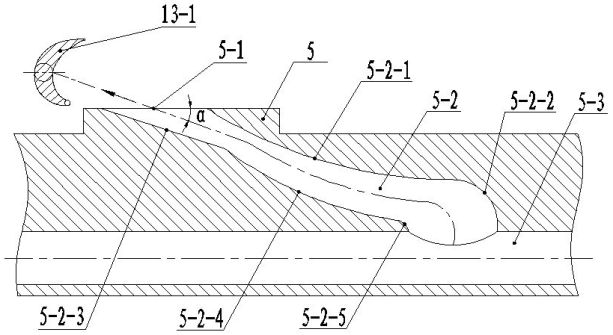
[0018] A water outlet joint 2 is provided on the pump body 1, and the air inlet nozzle 5 is fixedly connected to the lower end surface of the turbine casing 6, and the air inlet pipe 4 is fixedly connected to the circumferential outer surface of the air inlet nozzle 5, and the inside of the air inlet nozzle 5 There is a main air flow channel 5-3, and the main air flow channel 5-3 extends upward evenly with N sub-air flow channels 5-2. In this embodiment, N=4, and there are four nozzles 5-1 a...


PUM


Abstract

The invention relates to a novel turbo-type pneumatic submersible pump with multiple nozzles, which comprises a pump body, a turbo casing, a turbo cover plate, a rotary shaft, a turbo, a supporting device, a sealing socket, a water wheel, a pump cover and an anti-fouling seat. A water outlet joint is arranged on the pump body, an annular air inlet nozzle is fixedly connected to the lower end face of the turbo casing, an air inlet pipe is fixedly connected to the circumference surface of the air inlet nozzle, a main airflow passage communicated with the air inlet pipe inside the air inlet nozzle circumferentially, N sub airflow passages are uniformly distributed on the main airflow passage in an upward extending manner, the N is the natural number larger than or equal to 2 and smaller than or equal to 6, and nozzles which are communicated with the sub airflow passages and disposed in vent holes on the turbo casing are arranged at the upper end of the air inlet nozzle. The novel turbo-type pneumatic submersible pump with multiple nozzles is long in service life, simple in structure, low in cost and capable of realizing production in batch. Power of the pneumatic submersible pump is increased by the common airflow passage and the multiple nozzles. Noise is lowered by the aid of a silencer. Energy conversion rate is high due to the high-efficiency turbo which is cast precisely integrally. Due to a composite impeller, the pneumatic submersible pump can be adaptable to sewage containing large-particle impurities, and is high in flow and lift.

Description

technical field [0001] The invention relates to a novel multi-nozzle turbine type pneumatic submersible pump, which belongs to the technical field of pneumatic water pumps. Background technique [0002] Existing pneumatic submersible pumps are generally divided into three types: vane pumps, turbo pumps and gear pumps, which are generally composed of air motors, submersible pumps and mufflers. The air motor is mainly composed of an air intake device and a turbine device, and the submersible pump is mainly composed of a pump body and a water wheel. The vane pump was used early and widely because of its relatively high flow rate and head, but because of the sliding friction between the vane and the cylinder and between the vane and the guide groove, even if it is equipped with a lubricator, it needs to be repaired after less than ten days of continuous use. ; Although the turbo pump does not have the above problems, it generally has low flow rate and head flow rate, and poor s...

Claims


Application Information

Patent Timeline
Patent Type & Authority Applications(China)
IPC IPC(8): F04D13/04F04D29/22F04D29/66F01D15/08F01D9/02F01D25/00
Inventor 周正元
Owner CHANGZHOU COLLEGE OF INFORMATION TECH
Why Eureka
Try Eureka