Corrugated pipe ball valve

A technology of bellows and ball valves, applied in valve details, valve devices, shaft seals, etc., can solve problems such as normal use of bellows, damage of bellows, unsuitable torsion deformation of bellows, etc., to achieve long-term safe and reliable use and quick maintenance Convenience, solve the effect of medium leakage

Inactive Publication Date: 2012-07-18
CHAODA VALVE GRP
View PDF6 Cites 3 Cited by
  • Summary
  • Abstract
  • Description
  • Claims
  • Application Information

AI Technical Summary

Problems solved by technology

However, the switch of the ordinary ball valve is realized by the 90° rotation of the valve stem. When the ordinary ball valve adopts the bellows to seal the valve stem, the bellows will be subjected to torsional deformation instead of telescopic deformation during the opening and closing of the valve. , the bellows are not suitable for torsional deformation, therefore, during the switching process of the ball valve, the bellows must be damaged and fail due to torsional deformation
At present, in order to solve this problem, there have been many solutions, such as the bellows ball valve with the publication number CN101832401A, which fixes the bellows with the transmission cover and the transmission screw. Although the bellows can be used, due to structural defects, it increases Transmission cover and other leakage points; public number CN101629639A lifting rod bellows ball valve, although the bellows can be stretched up and down without twisting, but the spiral groove structure inside the valve is very prone to failure, and the valve seat structure The restrictions make it impossible to carry out online maintenance, and there is no description of the structure of the bellows, and ordinary bellows cannot be used normally under high temperature and high pressure, so this solution cannot be safe, reliable and long-term in high-risk media and environments usage of

Method used


Image

  • Corrugated pipe ball valve
  • Corrugated pipe ball valve
  • Corrugated pipe ball valve

Examples


Embodiment Construction

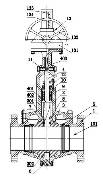
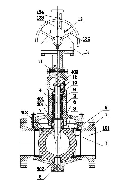
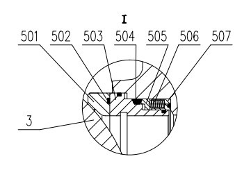
[0017] like figure 1 , 2 , 3 shows a bellows ball valve, including valve body 1, valve cover 2, ball 3, valve stem 4, valve cover 2 is fixed on valve body 1, and ball 3 is installed in the inner cavity of valve body 1 On the flow channel 101, a sealing valve seat 5 is provided between the sphere 3 and the valve body 1, the valve stem 4 passes through the valve cover 2 and is connected with the sphere 3 in the valve body 1, and the upper and lower ends of the sphere 3 are provided with coaxial valves. The upper shaft hole 301 and the lower shaft hole 302, the upper shaft hole 301 of the sphere 3 is a through hole, the lower shaft hole 302 of the sphere 3 is a blind hole, the central axis of the upper shaft hole 301, the lower shaft hole 302 and the valve body 1 The central axis of the inner chamber flow channel 101 is perpendicular to each other, and the vertical intersection point is the center of the sphere 3. The lower end of the valve body 1 is pierced with a lower shaft 6...


PUM


Abstract

The invention discloses a corrugated pipe ball valve, comprising a valve body, a valve cover, a ball body and a valve rod, wherein the upper end and the lower end of the ball body are provided with an upper shaft hole and a lower shaft hole in coaxial arrangement, a lower shaft in rotation matching with a lower shaft hole of the ball body passes through the lower end of the valve body, the lower end of the valve rod is provided with an extending end in a spirally twisted shape, the spiral extending end of the valve rod passes through an upper shaft hole of the ball body, a locking pin is arranged between the spiral extending end of the valve rod and the upper shaft hole of the ball body, and an adjusting ring is arranged between the ball body and the valve cover; the adjusting ring is sleeved on the spiral extending end of the valve rod to form the limiting clamping with the external end surface of the upper shaft hole on the ball body, a corrugated pipe is arranged between the valve rod and the valve cover, the valve cover is also provided with a guide pin, the valve rod is provided with a guide groove matched with the guide pin, and the valve rod can only move in a straight line up and down under the matching rotation of the guide pin and the guide groove. By using above structure, the ball valve can be maintained in an online manner, is free of leakage, high in environmental protection, and safe and reliable in long term usage.

Description

technical field [0001] The invention relates to a valve, in particular to a bellows ball valve. Background technique [0002] Valves used in petroleum, petrochemical, chemical, nuclear power and other industrial installations usually contain high-temperature, high-pressure, high-pollution, flammable, explosive, highly toxic, and even radioactive and other high-risk characteristics. Once leaked or distributed to In the atmosphere, it will cause immeasurable harm. Therefore, for straight-stroke valves, such as gate valves and globe valves, in addition to conventional packing seals, bellows sealing methods are added to the valve stem seals to prevent external leakage of the internal medium of the valves. However, the switch of the ordinary ball valve is realized by the 90° rotation of the valve stem. When the ordinary ball valve adopts the bellows to seal the valve stem, the bellows will be subjected to torsional deformation instead of telescopic deformation during the opening...

Claims


Application Information

Patent Timeline
Patent Type & Authority Applications(China)
IPC IPC(8): F16K5/06F16K37/00F16K41/10
Inventor 叶建中邱晓来王汉洲黄明金吴寿敬
Owner CHAODA VALVE GRP
Why Eureka
Try Eureka