
Lateral entering type backlight module

A side-entry backlight and module technology, which is applied in the field of side-entry backlight modules, can solve the problems of reducing uniformity, affecting the light intensity of the module, and causing light decay, so as to reduce the degree of color shift, uniformly disperse light, and Reduce the effect of hotspots

Inactive Publication Date: 2012-07-18
SHENZHEN CHINA STAR OPTOELECTRONICS TECH CO LTD
View PDF4 Cites 8 Cited by
  • Summary
  • Abstract
  • Description
  • Claims
  • Application Information

AI Technical Summary

Problems solved by technology

[0004] 1. When the light emitted by the light source chip passes through the phosphor, there is a difference in optical path, resulting in serious color shift
[0005] 2. The white light emitted by the WLED passes through the light guide plate with a flat side, and the refraction that occurs when the light path is sparse to light dense makes the light concentrated and reduces the uniformity
[0006] 3. It is easy to cause serious focus points due to uneven light mixing between LEDs
[0007] 4. During the use of WLED as a backlight source, the heat generated by the LED light source chip is easy to heat the phosphor powder, causing light decay, and the luminous efficiency of the phosphor powder is seriously reduced, which affects the light intensity of the module.
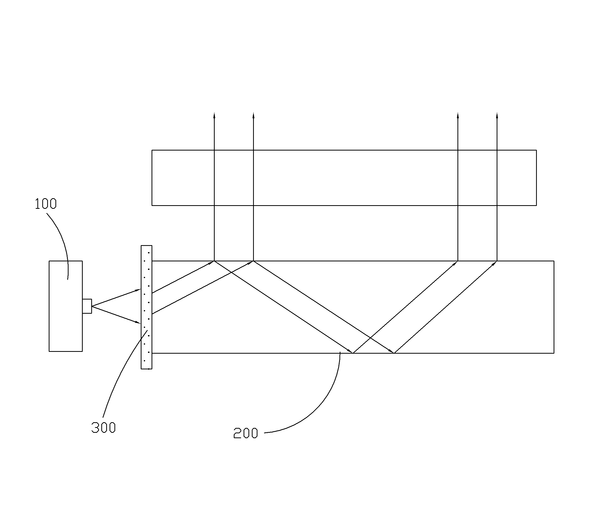
[0008] To solve the above problems, such as figure 1 As shown, an existing edge-lit backlight module includes a light source module 100 that emits blue light and a light guide plate 200. The light incident surface of the light guide plate 200 is provided with a fluorescent powder for being excited by blue light to generate white light. The phosphor film 300, the phosphor film 300 includes phosphor and colloid, and the phosphor film 300 is set separately from the light source module 100, which can effectively avoid the light decay phenomenon caused by the phosphor being heated, but fails to solve the problem of uneven light mixing, resulting in serious spotlight problem

Method used


Image

  • Lateral entering type backlight module
  • Lateral entering type backlight module
  • Lateral entering type backlight module

Examples


Embodiment Construction

[0021] In order to further illustrate the technical means adopted by the present invention and its effects, the following describes in detail in conjunction with preferred embodiments of the present invention and accompanying drawings.

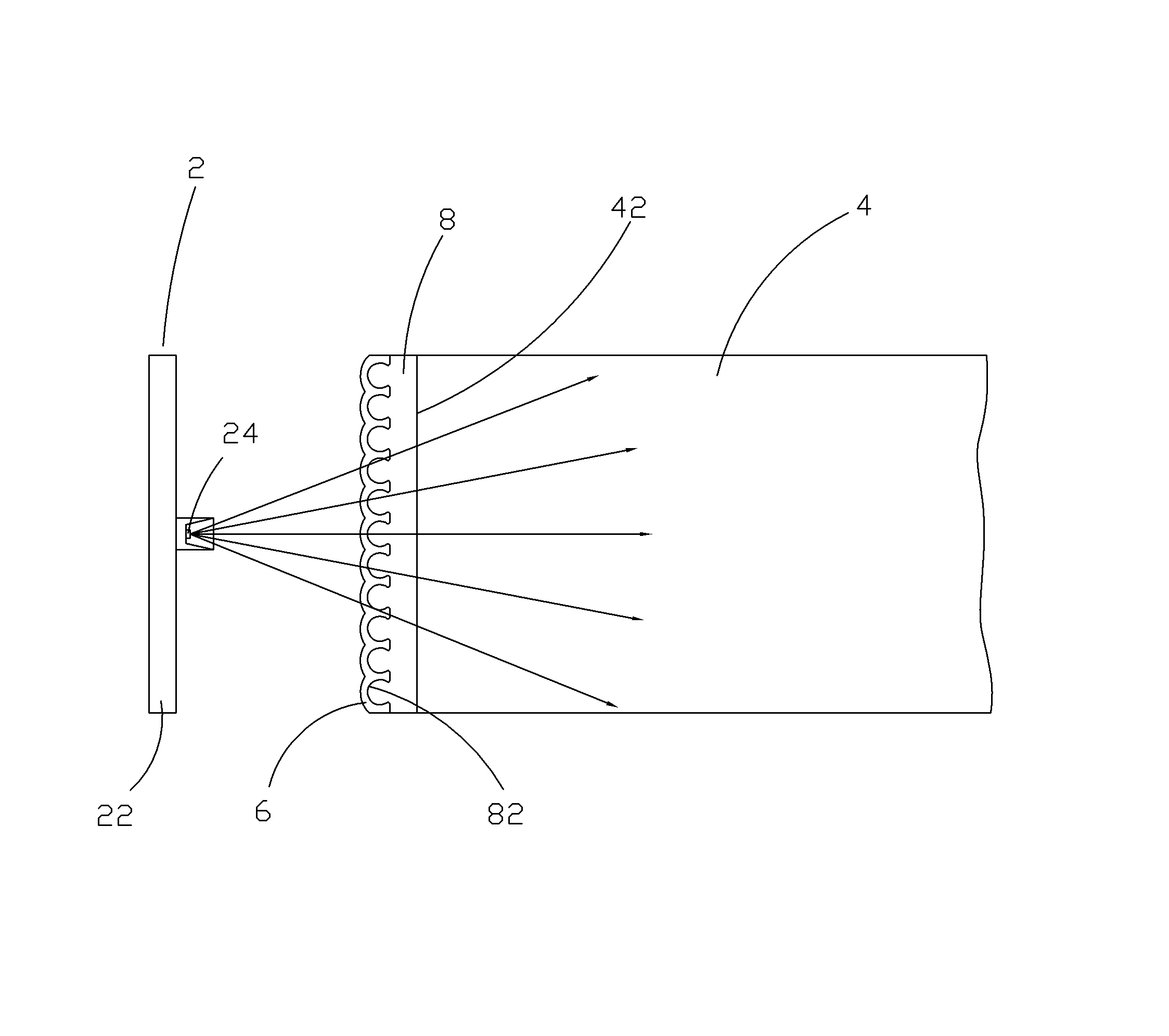
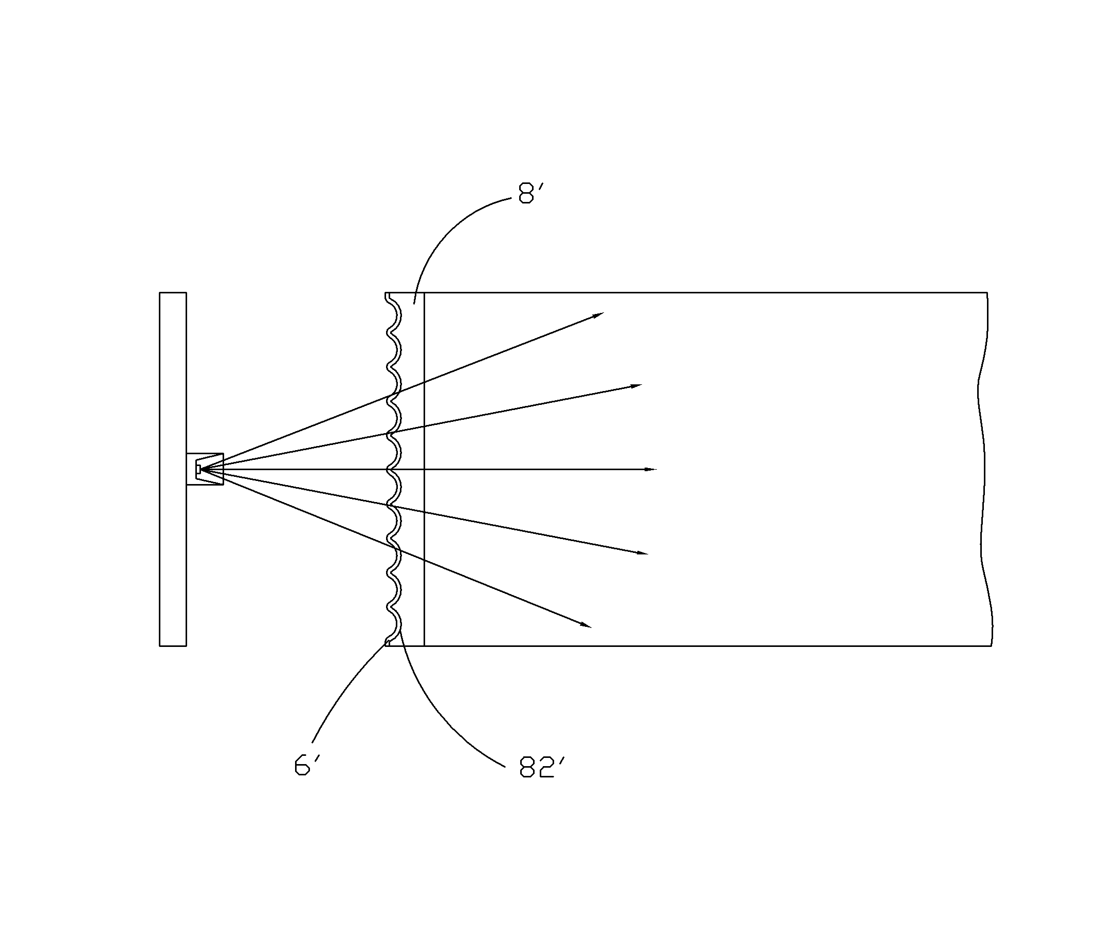
[0022] Such as figure 2 As shown, the side-type backlight module provided by the present invention includes: a backlight 2 for emitting blue light, a light guide plate 4, and a phosphor layer 6, the light guide plate 4 includes a light incident surface 42, and the phosphor layer 6 is arranged on the light incident surface 42 of the light guide plate 4 through an adhesive layer 8. The backlight source 2 preferably includes a circuit board 22, and several lamps for emitting blue light that are arranged on the circuit board 22 and are electrically connected to the circuit board 22. The LED chips 24 and the backlight 2 are arranged on the side of the light guide plate 4 corresponding to the light incident surface 42 , and several LED chips 24 of ...


PUM


Abstract

The invention provides a lateral entering type backlight module, which comprises a backlight source for emitting blue light, a light guide plate and a fluorescent powder layer, wherein the light guide plate comprises a light entering surface, the backlight source corresponding to the light entering surface is arranged on the side of the light guide plate, the fluorescent powder layer is arranged on the light entering surface of the light guide plate through an adhesive layer, the end surface of the adhesive layer contacting with the fluorescent powder layer is a smooth and continuous curved surface, the fluorescent powder layer is arranged along the curved surface, the fluorescent powder layer is excited by the blue light emitted by the backlight source to generate white light, and the white light penetrates through the adhesive layer and enters the light guide plate. The service lives of the module and the backlight source can be prolonged, the color cast degree of the module is reduced, light is scattered more evenly, condensation points are decreased, and uniformity of the light guide plate is improved.

Description

technical field [0001] The invention relates to the field of liquid crystal displays, in particular to a side-entry backlight module. Background technique [0002] The liquid crystal display device is referred to as LCD (Liquid Crystal Display). Its working principle is to place liquid crystal molecules between two parallel glasses. , to refract light to produce a picture. Since the liquid crystal display device has many advantages such as thin body, power saving, and no radiation, it has been widely used. Most of the liquid crystal display devices currently on the market are backlight liquid crystal displays, which generally include a liquid crystal panel and a backlight module. Backlight modules can be divided into side-type backlight modules and direct-type backlight modules according to the incident position of the light source, so as to provide backlight to the liquid crystal display. The structure of the existing side-entry backlight module generally includes a back...

Claims


Application Information

Patent Timeline
Patent Type & Authority Applications(China)
IPC IPC(8): F21S8/00F21V17/00G02F1/13357F21Y101/02
CPCG02B6/0025G02B6/0011F21V17/00F21S8/00G02F1/133615
Inventor 王烨文
Owner SHENZHEN CHINA STAR OPTOELECTRONICS TECH CO LTD
Learn More