
Reflector, backlight module and television set

A technology of backlight module and reflector, which is applied in the field of television, can solve the problems of insufficient light mixing distance, large loss of light source, and large light emitting angle of LED lights, etc., so as to improve the contrast and resolution of dynamic areas and improve the utilization rate of light energy , Improve the effect of comprehensive performance

Active Publication Date: 2012-07-18
GUANGDONG HISENSE ELECTRONICS CO LTD
View PDF6 Cites 0 Cited by
  • Summary
  • Abstract
  • Description
  • Claims
  • Application Information

AI Technical Summary

Problems solved by technology

[0005] Due to the large light emitting angle of the LED (close to 180°), it is difficult to directional control its illuminated range on the screen
[0006] The commonly used method to solve the above problems is to increase the number of LED lights, or add lenses to the LED lights above the reflector to solve the problems of insufficient light mixing distance and low light efficiency. Competitive in the market
[0007] In the process of realizing the present invention, the inventors found that the prior art has at least the following problems: the planar reflector has no ability to restrain the light beam, resulting in a large exit angle of light, more light scattered around, and loss of light source. Larger, low light source utilization; due to poor light efficiency, a large mixing distance is required, which makes the TV very thick and affects the aesthetics of the TV. At the same time, due to the large light-emitting angle of the LED light, it is not convenient for 3D Control of the dynamic area of ​​the backlight module in technology

Method used


Image

  • Reflector, backlight module and television set
  • Reflector, backlight module and television set
  • Reflector, backlight module and television set

Examples


Embodiment 1

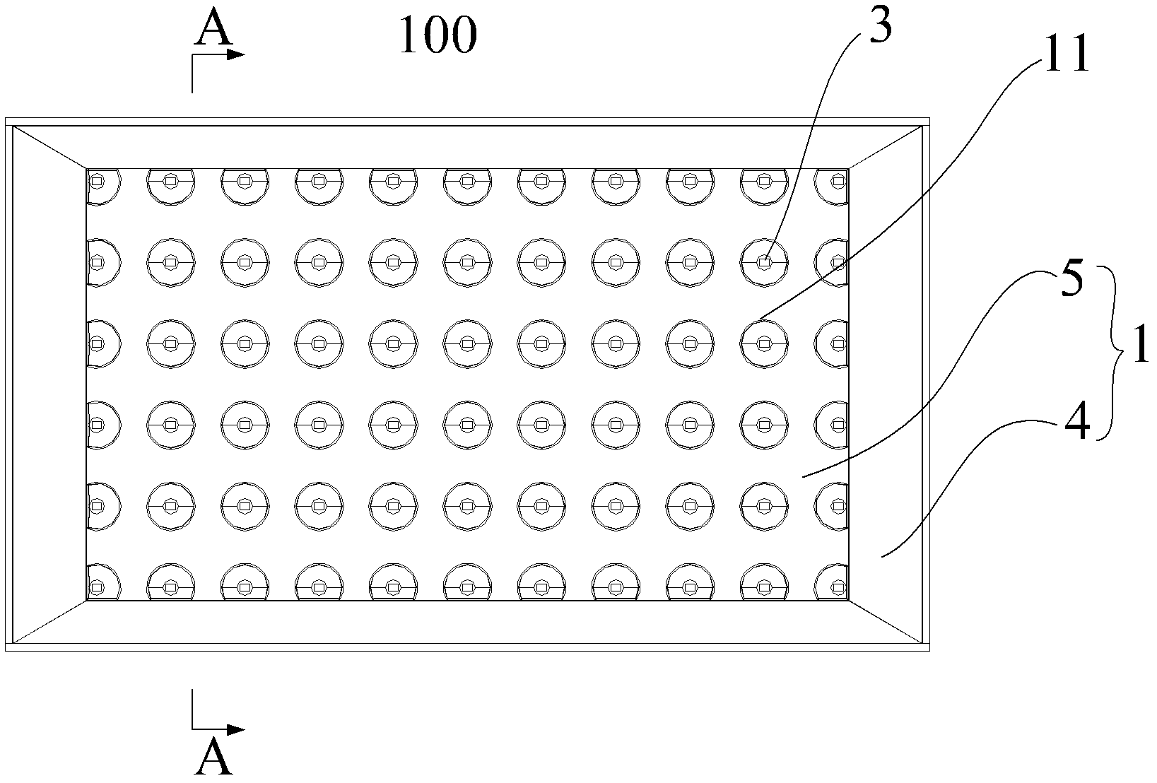
[0032] Figure 1 to Figure 3 A schematic structural view of the backlight module of the present invention is shown.

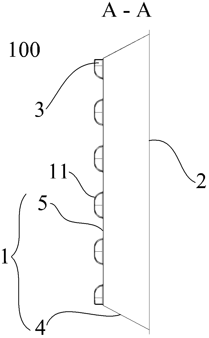
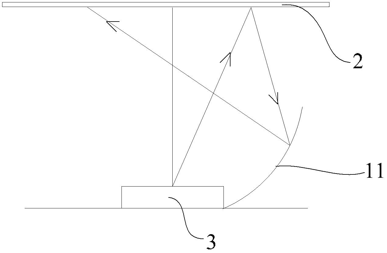
[0033] in, figure 1 is a schematic structural view of an embodiment of the backlight module according to the present invention, figure 2 yes figure 1 Schematic diagram of the sectional view along A-A in the middle, image 3 yes figure 1 Schematic diagram of the effect of the reflector on the light beam shown in .

[0034] Such as Figure 1 to Figure 3 As shown, the present invention also provides a backlight module 100, including a diffuser plate 2 and a reflective sheet, the bottom of the groove 11 of the reflective sheet is provided with a light-emitting element 3, and the opening end of the groove 11 faces the diffuser plate.

[0035] A reflective sheet provided by the present invention includes a reflective sheet body 1 , the reflective sheet body 1 includes a reflective sheet body bottom 5 and a reflective sheet body side 4 , and the reflective she...

Embodiment 2

[0079] The present invention also provides a TV (not shown in the figure), including the above-mentioned backlight module 100 .

[0080] Aiming at the problems existing in the current TV backlight module, the present invention proposes a plan to optimize the reflection sheet from a planar state to a three-dimensional foaming type.

[0081] In this program, the most critical points are:

[0082] The reflective sheet provided by the present invention includes a reflective sheet body 1 , and a groove 11 is provided at the bottom 5 of the reflective sheet body.

[0083] Preferably, the bottom 5 of the reflecting sheet body and the groove 11 are integrally formed by foaming.

[0084] Such as image 3 As shown, the present invention utilizes the contraction of the light beam divergence angle by each foaming groove 11 to increase the light effect within a small area of ​​each lamp, thereby increasing the light effect of the entire backlight.

[0085] After the light emitted by the...


PUM


Abstract

The invention provides a reflector. The reflector is characterized in that the reflector comprises a reflector body and a groove disposed on the reflector body. The invention also provides a backlight module and a television set comprising the backlight module. According to the technical scheme provided by the invention, the light utilization rate can be improved effectively by restricting the emergent light angle of the LED (light emitting diode) lamp through a groove in a small range of each LED lamp. Meanwhile, the energy distribution in each direction can be controlled by controlling the groove shape so as to improve the freedom of LED lamp arrangement to a certain extent. The restriction effect of the groove to the light source can also solve the problem of insufficient light mixing to a certain extent so as to solve the problem of subjective light shadow existing in the common direct-type backlight module; in addition, the requirement of 3D display for dynamic control of the backlight module area is well met, the contrast and resolution of the dynamic area are enhanced, and the comprehensive performance of 3D display equipment is improved.

Description

technical field [0001] The invention relates to the field of electronic products, in particular to a reflection sheet, a backlight module and a television. Background technique [0002] In the direct-type LED (Light Emitting Diode) module, the LED light is attached to the plane of the entire backplane. The matching reflector is also attached to the large plane of the back plate, and then emits light through the diffusion plate and other optical films. [0003] This kind of reflective sheet directly attached to the plane of the backplane generally has a planar structure. Under certain energy conditions, due to the lack of restraint on light, the angle of light emission is relatively large, and more light is scattered to the surroundings. The loss of light is also large, and the utilization rate of the light source is low; at the same time, due to the subjective requirement (that is, the user watches the TV screen from the front of the TV), the light mixing distance is also r...

Claims


Application Information

Patent Timeline
IPC IPC(8): F21V7/00F21S8/00H04N5/64F21Y101/02F21Y105/16F21Y115/10
Inventor 文喜平邵坤高上张智睿宋志成
Owner GUANGDONG HISENSE ELECTRONICS CO LTD
Features
  • Generate Ideas
  • Intellectual Property
  • Life Sciences
  • Materials
  • Tech Scout
  • Unparalleled Data Quality
  • Higher Quality Content
  • 60% Fewer Hallucinations
Learn More