Contour microscopic method and device

A technology for profiling and detecting optical fibers, which is applied in the field of microscopic methods and devices for profiling, can solve the problems of being unable to meet the super-resolution requirements of micro-scale structures and fail to improve the lateral resolution capability of the system, achieving remarkable lateral resolution, simple structure, The effect of horizontal resolution improvement

Inactive Publication Date: 2012-07-18
ZHEJIANG UNIV
View PDF3 Cites 11 Cited by
  • Summary
  • Abstract
  • Description
  • Claims
  • Application Information

AI Technical Summary

Problems solved by technology

Some patents have studied the use of differential confocal method to improve the axial resolution of the system. The axial resolution has been significantly improved, but the lateral resolution of the system has not been improved.
[0006] Therefore, t

Method used


Image

  • Contour microscopic method and device
  • Contour microscopic method and device
  • Contour microscopic method and device

Examples


Embodiment 1

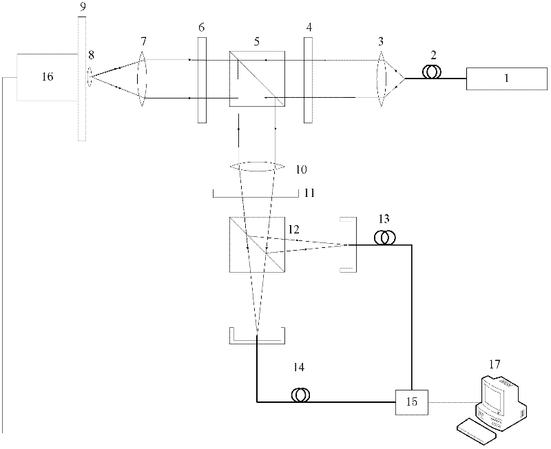
[0054] Such as figure 1 As shown, a microscopic device of a profile includes: a laser 1, a single-mode fiber 2, a first collimator lens 3, a first polarizer 4, a first polarizing beam splitter 5, a quarter wave plate 6, Second lens 7, sample platform 9, third lens 10, half-wave plate 11, second polarization beam splitter 12, second detection fiber 13, first detection fiber 14, differential detector 15, nano-translation stage 16, main control computer 17.

[0055] Wherein, the laser 1 emits a laser beam, and the single-mode fiber 2, the first collimating lens 3, the first polarizer 4, the first polarizing beam splitter 5, the quarter-wave plate 6 and the second lens 7 are sequentially arranged on the laser beam. on the optical axis of the beam path. The exit end face of the single-mode optical fiber 2 is located at the object focus of the first collimating lens 3, the single-mode optical fiber 2 and the first collimating lens 3 collimate the laser beam, and the first polarize...

Embodiment 2

[0069] use figure 1 When the shown device carries out the microscopy of the profile, in step (4), the fiber end face of the first detection fiber 14 and the fiber end face of the second detection fiber 13 move vertically along the same direction on the plane where they are respectively (simultaneously upward move or move downward at the same time), correspondingly, in subsequent steps (5)-(7), the surface of the sample to be tested is scanned vertically.

Embodiment 3

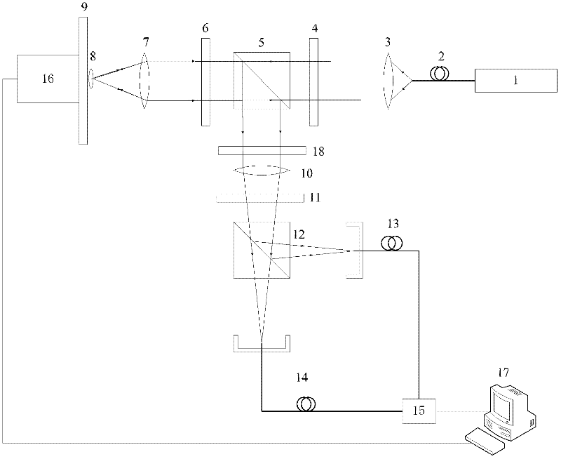
[0071] Such as figure 2 The micro-device shown in the profile is only different from Embodiment 1 in that the device also includes a 0 / π phase plate 18, wherein the 0 / π phase plate 18 is placed between the first polarizing beam splitter 5 and the third lens Between 10, the 0 / π phase division line of the 0 / π phase plate 18 passes through the center of the beam obtained by focusing the third lens 10 and is perpendicular to the center of the fiber end face of the first detection fiber 14 and the fiber end face of the second detection fiber 13 The connection formed by the center.

[0072] use figure 2 The microscopic method that the shown device realizes profile is also roughly the same as the method in Example 1, and its difference is only that step (4) is replaced as follows:

[0073] (4) First place a 0 / π phase plate 18 between the first polarizing beam splitter 5 and the third lens 10, and the 0 / π phase dividing line of the 0 / π phase plate 18 passes through the beam obtain...


PUM


Abstract

The invention discloses a contour microscopic method and device. The device comprises a laser, a single-mode optical fiber, a first collimating lens, a first polarizer, a first polarization beam splitter, a 1/4 wave plate, a second lens, a third lens, a 1/2 wave plate, a second polarization beam splitter, a first detection optical fiber, a second detection optical fiber, a differential detector, a master computer, a nano translation table and a sample platform used for placing a sample to be detected. According to the invention, a contour image of an object is obtained by virtue of a transverse difference, and transverse resolution of a system is effectively improved. The contour microscopic device disclosed by the invention has a simple structure, the transverse resolution is obviously improved and can reach up to 200nm or below, and the contour microscopic device disclosed by the invention can be applied to the optical microscopy field and nano-scale high-accuracy detection, measurement and manufacturing fields.

Description

technical field [0001] The invention belongs to the field of optical super-resolution microscopy, in particular to a microscopic method and device for contours. Background technique [0002] With the development of science and technology, people are constantly pursuing smaller and smaller size structures and higher resolution capabilities, especially in the fields of microelectronics, aerospace, nanofabrication, life science and material engineering. and super-resolution requirements are increasingly urgent. [0003] In 1957, M. Minsky proposed the idea of ​​confocal microscope for the first time and applied for a patent in 1961 in order to eliminate the influence of scattered light produced by ordinary optical microscopes when detecting samples. Subsequently, many scholars such as T.Wilson and C.J.Sheppard conducted more detailed research on confocal microscopy imaging technology. After the 1990s, with the development and integration of computer technology and the product...

Claims


Application Information

Patent Timeline
IPC IPC(8): G01B11/24
Inventor 匡翠方王轶凡刘旭
Owner ZHEJIANG UNIV
Why Eureka
Try Eureka