Torque measuring system for motor coupling

A technology of torque testing and coupling, applied in the field of testing systems capable of testing the torque of motor couplings, it can solve problems such as difficult adjustments, driving safety accidents, complex test control systems, etc., and achieve the effect of accurate test data

Active Publication Date: 2012-07-18
BOMBARDIER NUG PROPULSION SYST CO LTD
View PDF6 Cites 4 Cited by
  • Summary
  • Abstract
  • Description
  • Claims
  • Application Information

AI Technical Summary

Problems solved by technology

At present, the torque test of the high-power traction motor couplings of railway locomotives and bullet trains introduced in my country also adopts this method, but this method has the following disadvantages: First, because the test site is generally far away from the production site, it is difficult Realize the full torque test for the traction motor coupling, and the general test site requires an area of ​​at least 500 square meters; second, the investment in a dedicated load test bench is huge, and a new load test system needs at least millions of yuan; third, Due to the complexity of the test control system, operators need at least one month of training to master the functional operation of the entire test system; the shortcomings of the dedicated load test bench make it difficult to test the full torque of the traction motor couplings of high-power locomotives and trains, especially Small and medium-sized enterprises under financial pressure
With the continuous improvement of my country's railway operating speed, the traction motor as the power and braking device of the traction system of locomotives and bullet trains, the quality of the press-fitting of the coupling of the traction motor must also ensure 100% qualified, otherwise, once a problem occurs, it will be Can cause serious driving safety accidents
Some domestic locomotive and motor vehicle traction motor manufacturers have realized this, and have begun to conduct torque tests on all couplings of traction motors produced in batches. However, due to the pressure of capital investment and production, they have not built special traction motor couplings. For the load test bench, if the traction motor coupling of locomotives and bullet trains with relatively loose structure can be replaced by axial pulling method, this torque testing method requires a special large-tonnage hydraulic three-jaw puller and a Two semi-circular drawing tools were tested, but there were difficulties in tool installation and puller position adjustment, which resulted in low production efficiency, and axial tension was used instead of circumferential torque test and pressure gauge readings had to be converted into tension, etc. This indirect measurement method will make the measurement error large; and for the compact traction motor coupling, there are disadvantages that the test work cannot be completed due to the inability to install the tooling; therefore, it is very necessary in the process of localization of high-power traction motors Looking for a traction motor coupling torque test system with simple structure, convenient operation, low investment cost and wide application range, so as to realize full torque test for high-power traction motor couplings to ensure the press-fitting of the couplings Quality, providing sufficient technical support for the driving safety of high-power locomotives and bullet trains

Method used


Image

  • Torque measuring system for motor coupling
  • Torque measuring system for motor coupling
  • Torque measuring system for motor coupling

Examples


Embodiment Construction

[0024] The present invention will be described in further detail below in conjunction with the accompanying drawings.

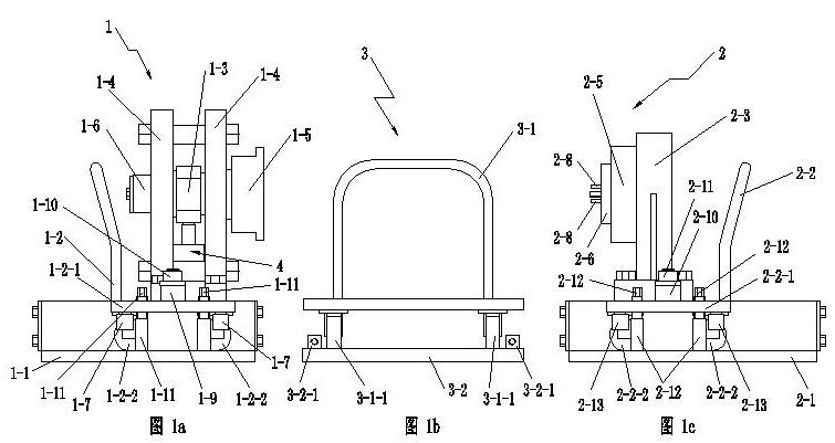
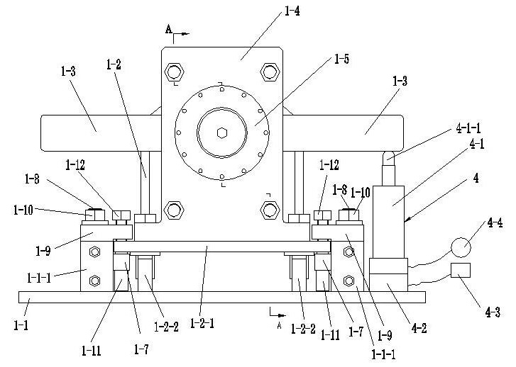
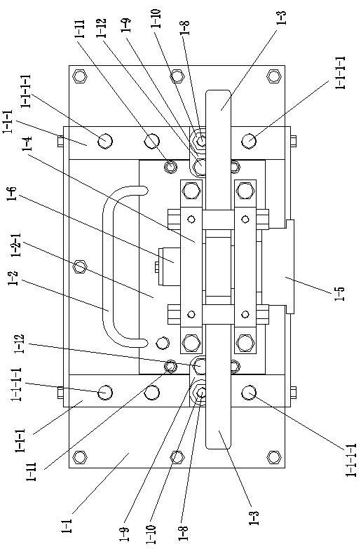
[0025] Such as Figure 1~8 As shown, a motor coupling torque testing system includes a lever device 1, a locking device 2 and a coupling moving device 3, and the coupling moving device 3 is located between the lever device 1 and the locking device 2; The lever device 1 includes a first base 1-1, a first mobile trolley 1-2, a lever 1-3, a first bracket 1-4 and a first flange 1-5, and the first bracket 1-4 is equipped with On the first mobile trolley 1-2, and on the first bracket 1-4, a bearing pin 1-6 is mounted in a rotational fit, and one end of the bearing pin 1-6 is connected with the first flange 1-5, so The lever 1-3 is fixed on the pin shaft 1-6, and the first mobile trolley 1-2 moves and cooperates with the first base 1-1; the first base 1-1 is also equipped with a force testing device 4 , and the force test device 4 is located under the shaft of the...


PUM


Abstract

The invention discloses a torque measuring system for a motor coupling, which includes a lever device, a locked rotor device and a coupling moving device, wherein the coupling moving device is arranged between the lever device and the locked rotor device; the lever device includes a first base, a first traveling vehicle, a lever, a first bracket and a first flange; the first bracket is mounted on the first traveling vehicle, and a pin shaft is rotationally mounted on the first bracket in a matched manner; one end of the pin shaft is connected with the first flange, and the lever is fixed on the pin shaft; a stress application testing device is also mounted on the first base, and is located below the lever body of the lever; the locked rotor device includes a second base, a second moving vehicle and a second bracket, wherein the second bracket is mounted on the second moving vehicle and is provided with a second flange; a third flange is mounted on the second flange, and a rolling stopper pin is mounted on the third flange; and the moving vehicles are glidingly matched with the bases. The torque measuring system not only has the advantages of simple structure and high measuring accuracy, but also is convenient to operate and low in investment cost.

Description

technical field [0001] The invention belongs to the technical field of traction motors of locomotives and motor vehicles, and in particular relates to a testing system capable of testing the coupling torque of a motor. Background technique [0002] The torque test of the traction motor couplings of foreign high-power locomotives and bullet trains with a motor capacity of more than 500KW after being pressed onto the motor shaft is only carried out during the type test of the new product prototype, and the test is carried out on a special load test bench. The torque test will not be performed on the motor couplings that will be mass-produced later. At present, the torque test of the high-power traction motor couplings of railway locomotives and bullet trains introduced in my country also adopts this method, but this method has the following disadvantages: First, because the test site is generally far away from the production site, it is difficult Realize the full torque test f...

Claims


Application Information

Patent Timeline
Patent Type & Authority Applications(China)
IPC IPC(8): G01N3/26G01N3/02G01M13/02
Inventor 何冠东
Owner BOMBARDIER NUG PROPULSION SYST CO LTD
Why Eureka
Try Eureka