
Ultrasonic circuit system for improving range-measuring accuracy

A circuit system and distance measuring circuit technology, applied in the directions of radio wave measurement system, sound wave re-radiation, measurement device, etc. The effect of the filter circuit

Active Publication Date: 2012-07-18
CHERY AUTOMOBILE CO LTD
View PDF11 Cites 16 Cited by
  • Summary
  • Abstract
  • Description
  • Claims
  • Application Information

AI Technical Summary

Problems solved by technology

[0002] For the ultrasonic ranging system, it is hoped that the detected echo is limited to a specific frequency range. Through actual tests, it is found that the echo voltage generated by the ultrasonic wave in the existing ultrasonic ranging system after encountering an obstacle returns Most of the signals are similar to sinusoidal signals, because the sinusoidal signals correspond to their positive and negative half cycles and include positive and negative voltage signals at the same time, usually such sinusoidal signals have mV levels, and need to be converted by subsequent amplifier circuits and comparators Therefore, when the mV sinusoidal signal is amplified by the subsequent amplification circuit and sent to the comparator, since the reference voltage of the comparator is usually a positive signal, only when the input signal of the comparator is positive and greater than the reference voltage of the comparator , the comparator will output a high level, so the negative signal in the sinusoidal signal will not generate a high level when it passes through the amplifying circuit and is sent to the comparator for comparison with the reference voltage of the comparator, resulting in an incorrect detection at this time. The negative signal in the ultrasonic sine echo signal and the ranging information it reflects seriously affect the ranging accuracy of the ultrasonic wave.

Method used


Image

  • Ultrasonic circuit system for improving range-measuring accuracy
  • Ultrasonic circuit system for improving range-measuring accuracy
  • Ultrasonic circuit system for improving range-measuring accuracy

Examples


Embodiment Construction

[0025] The technical scheme of the present invention is described in detail below in conjunction with accompanying drawing, but not limited thereto:

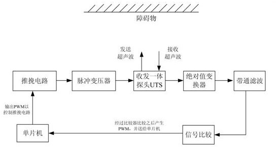
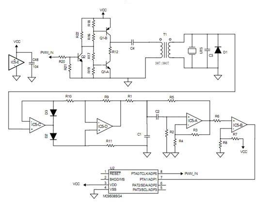
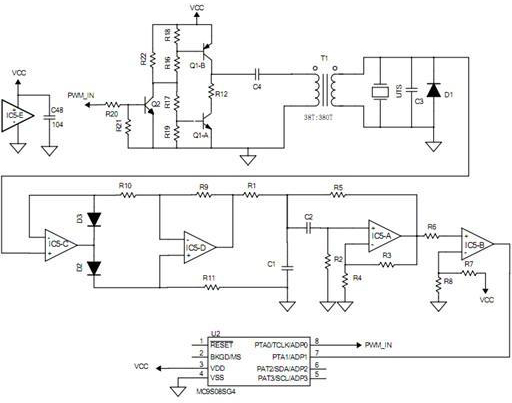
[0026] as attached figure 1 As shown, the ultrasonic circuit provided by the present invention mainly includes: a push-pull circuit, a pulse transformer T1, an ultrasonic probe UTS integrating transceiver, an absolute value converter, a band-pass filter amplifier, a comparator and a single-chip microcomputer, wherein the output terminal of the push-pull circuit is connected In the pulse transformer T1, it is used to change the voltage of the voltage source VCC into a pulse voltage and apply it to the pulse transformer T1. The output stage of the pulse transformer T1 is connected to the ultrasonic probe UTS to provide it with the driving pulse voltage for transmitting ultrasonic waves. The ultrasonic probe UTS The return detection signal is output to the precision absolute value converter, and the mV-level return signal is rectif...


PUM


Abstract

The invention provides an ultrasonic range-measuring circuit system, which comprises a drive circuit, an ultrasonic probe, an echo signal detection circuit and a singlechip, wherein the singlechip provides a starting signal for the drive circuit, the output end of the drive circuit is connected to the ultrasonic probe, an echo detection signal of the ultrasonic probe outputs to the echo signal detection circuit, the output end of the echo signal detection circuit is connected to the singlechip, the echo signal detection circuit can be used for rectifying the echo detection signal, and fully converting a negative signal into a positive signal, so that the conversion ensures that the ultrasonic echo signal is more precisely detected and the ultrasonic range-measuring precision is further improved, and meanwhile, an ultrasonic echo sine signal is subjected to full positive conversion so that the frequency of the ultrasonic echo sine signal is increased by one time, thus ultrasonic echo is more favorably subjected to frequency selecting and signal processing.

Description

technical field [0001] The invention relates to the field of ultrasonic ranging, and more specifically relates to an ultrasonic circuit system capable of improving the accuracy of ultrasonic ranging. Background technique [0002] For the ultrasonic ranging system, it is hoped that the detected echo is limited to a specific frequency range. Through actual tests, it is found that the echo voltage generated by the ultrasonic wave in the existing ultrasonic ranging system after encountering an obstacle returns Most of the signals are similar to sinusoidal signals, because the sinusoidal signals correspond to their positive and negative half cycles and include positive and negative voltage signals at the same time, usually such sinusoidal signals have mV levels, and need to be converted by subsequent amplifier circuits and comparators Therefore, when the mV sinusoidal signal is amplified by the subsequent amplification circuit and sent to the comparator, since the reference volta...

Claims


Application Information

Patent Timeline
IPC IPC(8): G01S7/52G01S15/08
Inventor 朱得亚邓飞贺周勇
Owner CHERY AUTOMOBILE CO LTD
Learn More