Optical path folding system based on polarization beam splitter plate and wave zone plates

A polarizing beam splitter and folding system technology, applied in optics, optical components, instruments, etc., can solve the problems of huge size, weight, and application limitations, and achieve the effects of compact and reasonable structure, lightweight design, and good processing technology

Inactive Publication Date: 2012-07-18
河南平原光电有限公司
View PDF0 Cites 4 Cited by
  • Summary
  • Abstract
  • Description
  • Claims
  • Application Information

AI Technical Summary

Problems solved by technology

For example, in flight simulation training and individual soldier simulation training, it provides real-time GPS navigation, road conditions, combat conditions, targets and other information and combat command informatio

Method used


Image

  • Optical path folding system based on polarization beam splitter plate and wave zone plates
  • Optical path folding system based on polarization beam splitter plate and wave zone plates

Examples


Embodiment Construction

[0007] The present invention will be further described below in conjunction with specific examples.

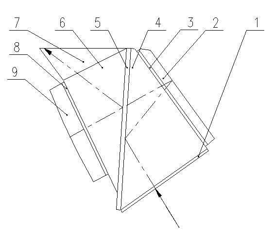
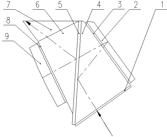
[0008] like figure 1 Shown, the present invention is by polarizer 1, the first prism 4, the first zone plate 3, reflecting mirror 2, polarization beam splitter 5, the second prism 6, the second zone plate 8, collimating objective lens 9, the first Triangular prism 7 is made up of, and wherein wherein collimating objective lens 9, second zone plate 8 and second prism 6 are glued together successively; The device 1 is glued; the reflector 2 is glued with the first zone plate 3; the three components are glued with the third prism 7.

[0009] The chief ray enters the first prism 4 through the polarizer 1, and returns to the first prism 4 after being reflected by the polarization beam splitter 5 close to the first prism 4. When the light exits from the first prism 4, it passes through the first zone plate 3 After entering the reflector 2, after being reflected by the reflector 2,...


PUM


Abstract

The invention discloses an optical path folding system based on a polarization beam splitter plate and wave zone plates, which is composed of a polarizer, a first prism, a first wave zone plate, a reflector, the polarization beam splitter plate, a second prism, a second wave zone plate, a collimator objective and a third prism. The collimator objective is adhered with the second wave zone plate and then adhered with the second prism, the polarization beam splitter plate is adhered with the first prism and then adhered with the polarizer, the reflector is adhered with the first wave zone plate, and the collimator objective, the polarization beam splitter plate and the reflector are respectively adhered with the third prism. All the components of the optical path folding system are made of cheap and common glass K9 materials which can be purchased easily, the optical path folding system is compact and reasonable in structure, good in processing technology and simple in assembling process and achieves the aim of being light in integral design.

Description

technical field [0001] The invention relates to an optical path folding system based on a polarization beam splitter and a zone plate, and belongs to the technical field of photoelectric comprehensive observation and aiming. Background technique [0002] A conventional optical system becomes bulky and bulky as the field of view of the system increases. For example, in flight simulation training and individual soldier simulation training, it provides real-time GPS navigation, road conditions, combat conditions, targets and other information and combat command information transmission systems for pilots, drivers, guns and rocket launchers, etc. In the optical system with strict requirements on the structural size of the system, the huge volume and weight greatly restrict its application. Therefore, it is very necessary to develop a light and compact optical system to overcome the defects of the traditional optical system in this respect. Contents of the invention [0003] ...

Claims


Application Information

Patent Timeline
IPC IPC(8): G02B17/08G02B27/28
Inventor 曹志亮王松伟谭瑞军李慧珍王曦赵路民何波辛玫李存建江楠高宇
Owner 河南平原光电有限公司
Why Eureka
Try Eureka