
OBU (On Board Unit) positioning method, positioning device and system based on DBF (Digital Beam Forming)

A positioning device and positioning method technology, applied in the field of intelligent transportation, can solve problems such as poor positioning accuracy, achieve the effects of reducing disputes, realizing precise positioning, and solving interference

Active Publication Date: 2012-07-18
BEIJING WANJI TECH
View PDF8 Cites 32 Cited by
  • Summary
  • Abstract
  • Description
  • Claims
  • Application Information

AI Technical Summary

Problems solved by technology

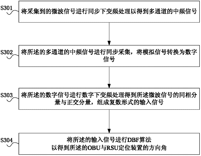
[0008] The embodiment of the present invention provides a DBF-based OBU positioning method, positioning device and non-stop charging system, by determining the direction angle between the OBU and different RSU positioning devices by receiving microwave signals sent by the OBU according to different RSU positioning devices, Furthermore, according to the position and direction angle of different RSU positioning devices, the precise positioning of the vehicle equipped with the OBU is realized, which solves the problem of poor positioning accuracy of the non-stop charging system in the prior art

Method used


Image

  • OBU (On Board Unit) positioning method, positioning device and system based on DBF (Digital Beam Forming)
  • OBU (On Board Unit) positioning method, positioning device and system based on DBF (Digital Beam Forming)
  • OBU (On Board Unit) positioning method, positioning device and system based on DBF (Digital Beam Forming)

Examples


Embodiment 1

[0103] Figure 9 It is a schematic diagram of two RSU positioning devices in the embodiment of the present invention when they are on the same straight line, by Figure 9 It can be seen that in the first embodiment, the two RSU positioning devices are arranged on the same straight line, and the direction of the antenna line array is the same as the direction of the straight line where the two RSU positioning devices are located.

[0104] Figure 10 The schematic diagram for positioning the OBU when the two RSU positioning devices are in the same line, by Figure 10 It can be seen that in the XY plane, A and B are 2s apart and both are on the X axis, the coordinates of point A are (-s, 0), the coordinates of point B are (s, 0), and P(x 0 ,y 0 ) is a point on the plane, and the included angle α between PA, PB and X-axis can be obtained by DBF algorithm 1 and alpha 2 .

[0105] Let the slope of the straight line where PA is located be k 1 , the slope of the straight line w...

Embodiment 2

[0117] Set the three RSU positioning devices on the same straight line, the antenna line array direction of RSU positioning device 1 and RSU positioning device 2 is the same, along the X-axis direction, the antenna line array direction of RSU positioning device 3 is the Z-axis direction, as Figure 11 shown. Figure 12 The schematic diagram for positioning the OBU when the three RSU positioning devices are in the same line, by Figure 12 It can be seen that the direction of the antenna array at point A and B is in the same direction as the X axis, and the direction of the antenna array at point C is in the same direction as the Z axis. Therefore, the angle between PA, PB and X axis and the angle between PC and Z axis can be obtained. horn. The distance between A and B is 2s, then the coordinates of point A are (-s, 0, 0), the coordinates of point B are (s, 0, 0), point C is the origin, and the three-dimensional coordinates of point P (x 1 ,y 1 ,z 1 ) is the desired point. ...


PUM


Abstract

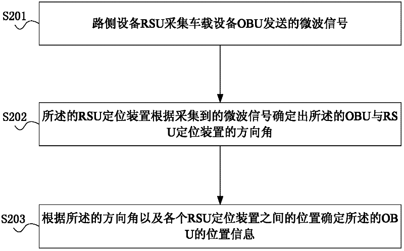
The embodiment of the invention provides an OBU (On Board Unit) positioning method, positioning device and electronic toll collection system based on DBF (Digital Beam Forming). The method comprises the following steps of: collecting a microwave signal transmitted by an on board unit (OBU) by using a road side unit (RSU), wherein the road side unit (RSU) comprises an RSU antenna, an RSU control device and at least two RSU positioning devices; determining direction angles between the OBU and the RSU positioning devices by using the RSU positioning devices according to the collected microwave signal; and determining position information of the OBU according to the direction angles and a position between the RSU positioning devices. Through determining the direction angles between the OBU and the different RSU positioning devices according to the microwave signal received by the different RSU positioning devices and transmitted by the OBU and accurately positioning the vehicle mounted with the OBU according to the positions and direction angles of the different RSU positioning devices, the problem of poor positioning accuracy of the electronic toll collection system in the prior art is solved.

Description

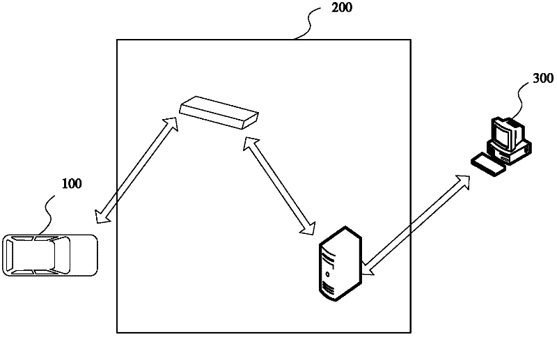
technical field [0001] The present invention relates to intelligent traffic technology, in particular to non-stop toll collection technology, specifically a DBF-based OBU positioning method, a positioning device and a non-stop toll collection system. Background technique [0002] The non-stop charging system is a special application in the field of intelligent transportation systems. It uses dedicated short-range wireless communication (DSRC: Dedicated Short-Range Communication) technology to realize the entire charging process, so that vehicles can keep driving during the entire charging process without parking. At present, this technology has been widely used in expressway toll collection. Such as figure 1 As shown, the existing expressway non-stop charging system mainly includes the following equipment: [0003] 1) Lane computer 300: responsible for controlling the state of the lane and completing information processing. [0004] 2) Road Side Unit (RSU, Road Side Unit)...

Claims


Application Information

Patent Timeline
IPC IPC(8): G07B15/06G01S5/02
Inventor 田林岩杨胜姚
Owner BEIJING WANJI TECH
Learn More