Electromagnetic relay suitable for automatic production and with reliable electroconductivity and assembling method thereof

An electromagnetic relay, a technology of electrical conductivity, applied in the direction of electromagnetic relays, electromagnetic relay details, relays, etc., can solve the problems of excessive heat generation of yoke iron, low conductivity of iron copper, and rise in temperature of relays, etc., to improve production efficiency, Simplify the effect of improving and reducing heat generation

Active Publication Date: 2012-07-18
XIAMEN HONGFA AUTOMOTIVE ELECTRONICS CO LTD
View PDF4 Cites 1 Cited by
  • Summary
  • Abstract
  • Description
  • Claims
  • Application Information

AI Technical Summary

Problems solved by technology

[0004] The moving springs of the above two clap-on electromagnetic relays are positioned and fixed by riveting with the two convex buds on the yoke iron. During the automatic assembly process, the moving spring is easy to break away from the convex buds of the yoke iron, causing defects; On the one hand, the moving spring is not directly connected to the lead-out pin, but conducts electricity through the yoke. Since the conductivity of iron is very low compared to copper, it is easy to cause excessive heat in the conductive part of the yoke, which will cause the relay to fail due to excessive temperature rise.

Method used


Image

  • Electromagnetic relay suitable for automatic production and with reliable electroconductivity and assembling method thereof
  • Electromagnetic relay suitable for automatic production and with reliable electroconductivity and assembling method thereof
  • Electromagnetic relay suitable for automatic production and with reliable electroconductivity and assembling method thereof

Examples


Embodiment Construction

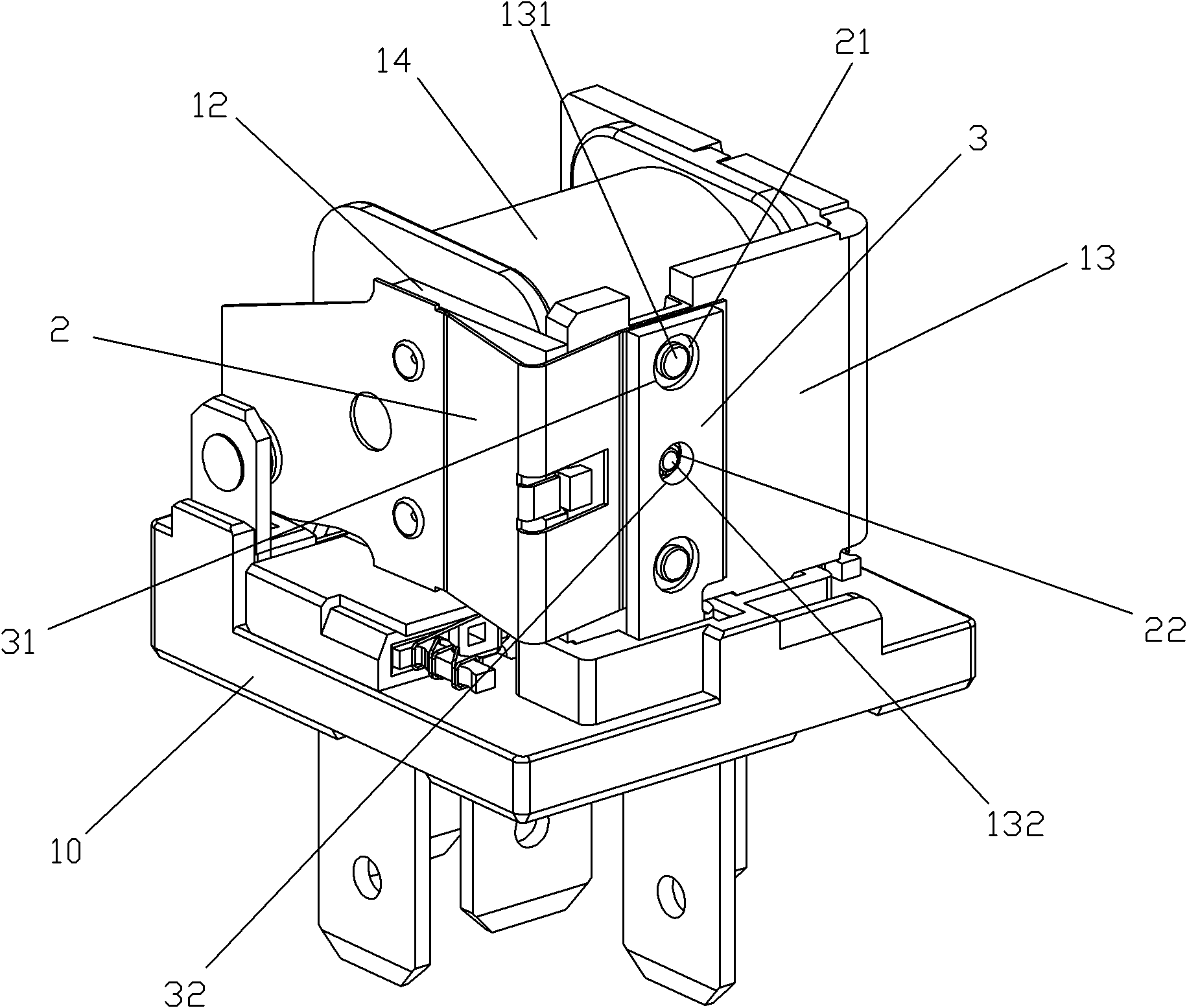
[0023] Examples, see Figure 3 to Figure 5 As shown, a kind of electromagnetic relay suitable for automatic production and reliable conductivity of the present invention includes a magnetic circuit part, a moving spring part, a lead-out pin part and a base 10; the magnetic circuit part, a moving spring part and a lead-out pin part are mounted on the base 10; the magnetic circuit part includes an iron core 11, an armature 12, a yoke 13 and a coil 14; the moving spring part includes a moving spring 2; 2 The two first protruding buds 131 fixed by riveting are provided with two first positioning holes 21 for matching with the two first protruding buds of the yoke on the moving spring 2; A second protruding bud 132, on the moving spring 2 is also provided with a clamping hole 22 for matching with the second protruding bud 132 of the yoke; The foot 3 is provided with two second positioning holes 31 that can be matched with the two first convex buds of the yoke; 1. The correspondin...


PUM


Abstract

The invention discloses an electromagnetic relay suitable for automatic production and with reliable electroconductivity and an assembling method of the electromagnetic relay. The electromagnetic relay comprises yoke, a movable spring and a movable spring leading pin, wherein the yoke is provided with a second bulge, and the movable spring is provided with a clamping hole correspondingly matched with the second bulge of the yoke; a second positioning hole correspondingly matched with a first bulge of the yoke is arranged on the movable spring leading pin; the movable spring is correspondingly matched with the first bulge and the second bulge of the yoke through a first positioning hole and the clamping hole to be positioned and clamped on the yoke; and the movable spring leading pin is arranged on the yoke by being matched with the first bulge of the yoke via the second positioning hole and performs riveting on the first bulge so that the movable leading pin, the movable spring and the yoke are fixed together, and the movable spring is clamped between the movable spring leading pin and the yoke. By adopting the structure, on one hand, the electromagnetic relay can eliminate the disadvantage that the movable spring is easily divorced from the bulges of the yoke in an automatic assembling process, and on the other hand, the electromagnetic relay can realize the effects of improving a current-carrying area, shortening a conducting path and reducing heat generation, thereby achieving the purposes of high-current and high-reliability electroconductivity.

Description

technical field [0001] The invention relates to an electromagnetic relay, in particular to an electromagnetic relay suitable for automatic production and reliable in conduction performance and an assembly method thereof. Background technique [0002] Relay is an automatic switching element with isolation function, which is widely used in communication, automobile, automatic control, household appliances and other fields, and is one of the most important control elements. With the requirements of modern industry for high production efficiency, high load current and high reliability of relays, the production method of relays has entered the era of automatic production, and the performance requirements have entered the era of high load and high reliability. [0003] The snap-in electromagnetic relay of the prior art usually includes parts such as a magnetic circuit part, a moving spring part, a lead-out pin, and a base part. It is composed of a moving spring and a moving conta...

Claims


Application Information

Patent Timeline
Patent Type & Authority Applications(China)
IPC IPC(8): H01H50/36H01H50/56H01H49/00
Inventor 吴子明
Owner XIAMEN HONGFA AUTOMOTIVE ELECTRONICS CO LTD
Why Eureka
Try Eureka