
Light emitting element

A light-emitting element and light wavelength technology, which is applied in the direction of electrical components, electric solid-state devices, semiconductor devices, etc., can solve the problems of difficulty in meeting the requirements of luminous efficiency, poor color stability of organic light-emitting diodes, etc., and achieve the effect of easy production and stable optical performance

Inactive Publication Date: 2012-07-18
AU OPTRONICS CORP
View PDF4 Cites 2 Cited by
  • Summary
  • Abstract
  • Description
  • Claims
  • Application Information

AI Technical Summary

Problems solved by technology

[0004] However, if there are three or more types of doping materials, it will be difficult to adjust these doping materials so that the luminous spectrum and luminous efficiency of the organic light-emitting diode meet the requirements, and the organic light-emitting diodes containing three or more doping materials The color stability of the diode is also poor under different driving voltages

Method used


Image

  • Light emitting element
  • Light emitting element
  • Light emitting element

Examples


Embodiment Construction

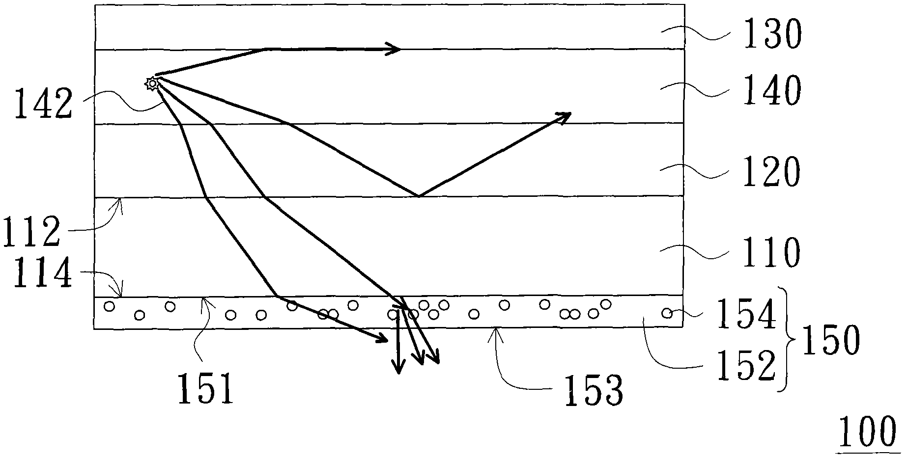
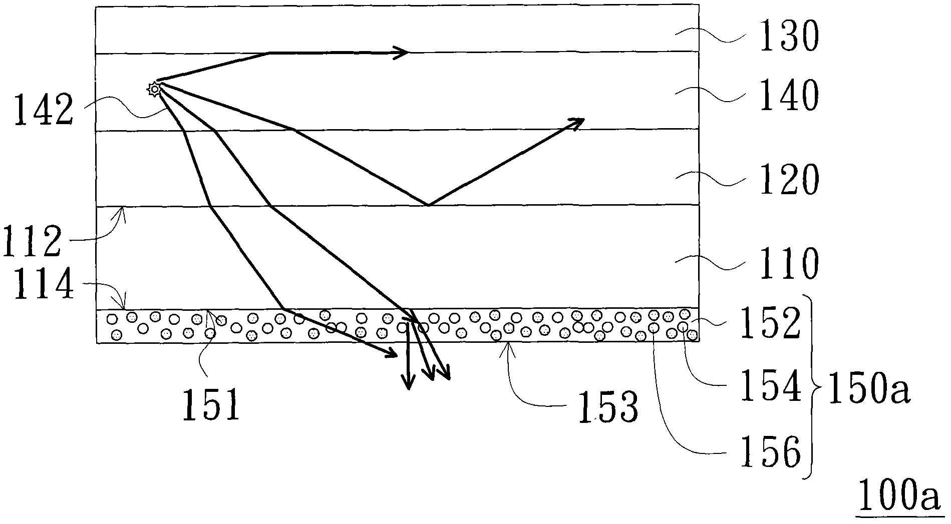
[0032] figure 1 It is a schematic diagram of a light emitting element according to an embodiment of the present invention. Please refer to figure 1 , the light emitting element 100 of this embodiment includes a transparent substrate 110 , a first electrode layer 120 , a second electrode layer 130 , a light emitting layer 140 and a light wavelength adjustment film 150 . The transparent substrate 110 can be a glass substrate or a plastic substrate, but not limited thereto. The transparent substrate 110 has a first surface 112 and a second surface 114 opposite to each other. The first electrode layer 120 is disposed on the first surface 112, and the first electrode layer 120 is a transparent electrode layer, such as an indium tin oxide (ITO) electrode layer or an indium zinc oxide (IZO) electrode layer etc. The second electrode layer 130 is opposite to the first electrode layer 120 , and the first electrode layer 120 and the second electrode layer 130 are positive and negativ...


PUM


Abstract

The invention provides a light emitting element, which comprises a transparent substrate, a first electrode layer, a second electrode layer, a light-emitting layer and a light wavelength adjusting film. The light-emitting layer comprises a first surface and a second surface opposite to each other. The first electrode layer is arranged on the first surface and the first electrode layer is a transparent electrode layer. The second electrode layer is arranged opposite to the first electrode layer. The light-emitting layer is arranged between the first electrode layer and the second electrode layer. The light wavelength adjusting film comprises a transparent layer and a plurality of fluorescent particles. The transparent layer comprises a light incident surface and a light exiting surface opposite to each other. The light incident surface is connected to the second surface. The light exiting surface is in contact with the outside air. The fluorescent particles are disposed in the transparent layer. The light-emitting element has better optical performance.

Description

technical field [0001] The present invention relates to a semiconductor electronic element, and in particular to a light emitting element. Background technique [0002] Organic light emitting diodes have the advantages of small size, long service life, and fast response time. In recent years, with the continuous improvement of organic light emitting diode (OLED) technology, organic light emitting diodes have been gradually applied in various Fields, such as flat light source or flat display, etc. [0003] In order to improve the color rendering index (CRI) of the organic light emitting diode and the performance of the index color R9, the known technology achieves the above purpose by adding a variety of dopant materials. [0004] However, if there are three or more types of doping materials, it will be difficult to adjust these doping materials so that the luminous spectrum and luminous efficiency of the organic light-emitting diode meet the requirements, and the organic li...

Claims


Application Information

Patent Timeline
IPC IPC(8): H01L51/52
Inventor 陈重嘉林俊良江伯轩
Owner AU OPTRONICS CORP
Learn More