Battery system formed by directly performing series-parallel connection on unit batteries
A single battery and battery system technology, applied in the direction of battery components, circuits, electrical components, etc., can solve the problems of non-removable and replaceable, unstable structure, poor reliability, etc., to avoid destructive and ensure good contact , to avoid the effect of poor reliability
- Summary
- Abstract
- Description
- Claims
- Application Information
AI Technical Summary
Problems solved by technology
Method used
Image
Examples
Embodiment 1
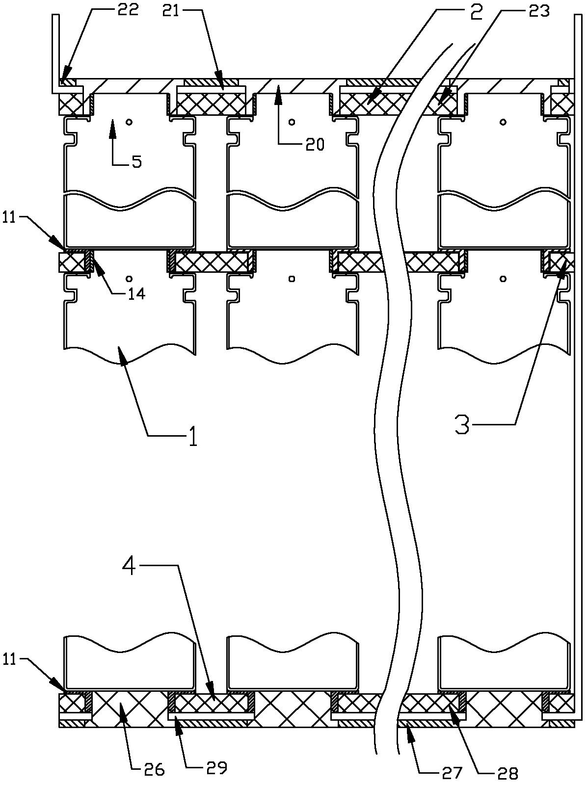
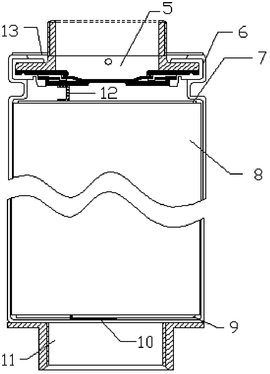
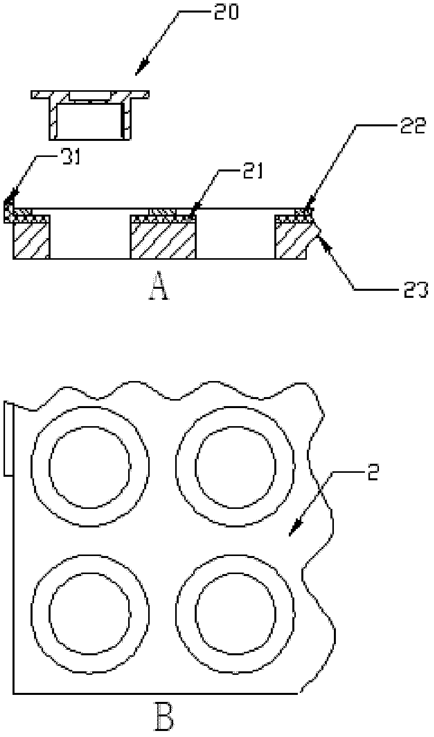
[0034] Such as figure 1 , 2As shown, a battery system that can directly use single cells connected in series and parallel, includes several single cells 1, positive pole plates 2, several intermediate pole plates 3 and negative pole plates 4, the positive pole plates 2, several intermediate pole plates A number of single cells 1 on the pole plate 3 and the negative pole plate 4 form a parallel battery pack respectively, and the battery system is formed in series between each parallel battery pack; the single battery 1 includes a cap 5, a casing 6, an upper gasket 7. Basic components such as winding core 8, lower gasket 9, negative pole lug 10, positive pole lug 12, first insulating gasket 13, etc., also include positive pole terminal 14, negative pole terminal 11; the positive and negative pole terminals 14, 11 is an annular columnar metal protruding from the bottom, the outer diameter of the annular columnar part of the positive terminal 14 is equal to the inner diameter of ...
Embodiment 2
[0047] This embodiment is the same as Embodiment 1, except that the positive pole plate 2, the middle pole plate 3, and the negative pole plate 4 all use PCB boards, and the upper and lower insulating layers in the PCB board correspond to the positive pole plates 2, the positive upper and lower insulating layers 22, 23, the negative upper and lower insulating layers 28, 27 of the negative plate 4, and the intermediate insulating layer 25 on the intermediate plate 3, and the metal copper layers in the PCB board correspond to the positive electrodes respectively. Positive and negative busbars 21 and 29 on the pole plate 2 , the negative pole plate 4 and the equipotential layer 24 on the intermediate pole plate 3 . In this way, the production process of each pole plate is simplified, and the production cost of the battery system is better lowered.
Embodiment 3
[0049] This embodiment is the same as embodiment 1, the difference is that, as Figure 7 As shown, a hole on the positive electrode plate 2 corresponding to the middle position of the battery system, several intermediate electrode plates 3 and the negative electrode plate 4 is not installed with a single battery 1, but is penetrated by a screw rod 33. The screw 33 is fastened on the positive electrode plate 2 through the first nut 34, and a second insulating gasket is provided between the first nut 34 and the positive electrode plate 2, and between the bottom of the screw 33 and the negative electrode plate 4 35 and reinforcing plate 36. In this embodiment, the battery system is fastened inwardly from the upper and lower ends by the screw and the reinforcing plate, further ensuring good contact of various parts of the entire battery system and structural reliability of the entire system.
PUM
 Abstract
Description
Claims
Application Information
 - R&D
- Intellectual Property
- Life Sciences
- Materials
- Tech Scout
- Unparalleled Data Quality
- Higher Quality Content
- 60% Fewer Hallucinations
Browse by: Latest US Patents, China's latest patents, Technical Efficacy Thesaurus, Application Domain, Technology Topic, Popular Technical Reports.
© 2025 PatSnap. All rights reserved.Legal|Privacy policy|Modern Slavery Act Transparency Statement|Sitemap|About US| Contact US: help@patsnap.com


