Automatic welding machine for DC (direct-current) power supply connector

An automatic welding machine, DC power supply technology, applied in the direction of circuits, connections, electrical components, etc., can solve the problems of low grinding efficiency, low wire stripping efficiency, poor welding operating environment, etc., to achieve high welding efficiency and improve processing. Efficiency and product quality, the effect of improving working conditions

Inactive Publication Date: 2012-07-18
东莞市双力数控设备有限公司
View PDF3 Cites 12 Cited by
  • Summary
  • Abstract
  • Description
  • Claims
  • Application Information

AI Technical Summary

Problems solved by technology

[0002] The existing DC power connector is welded on the end of the DC connector with two peeled cable bodies. Before welding, usually in order to improve the welding performance of the connector and the cable body, the DC power supply will be manually held. The joints are ground on a grinder, the grinding efficiency is not only low, but also the working environment is poor, a little carelessness is prone to work injuries; the cable body is also manually stripped on a simple wire stripping machine, the stripping efficiency is not high, and the operation are also prone to fatigue
After the joints are polished, hand-held joints and stripped wires are used for manual welding. The welding environment is relatively poor, and it is harmful to the health of the operator.

Method used


Image

  • Automatic welding machine for DC (direct-current) power supply connector
  • Automatic welding machine for DC (direct-current) power supply connector
  • Automatic welding machine for DC (direct-current) power supply connector

Examples


Embodiment Construction

[0018] The present invention will be described in detail below in conjunction with the accompanying drawings and specific embodiments.

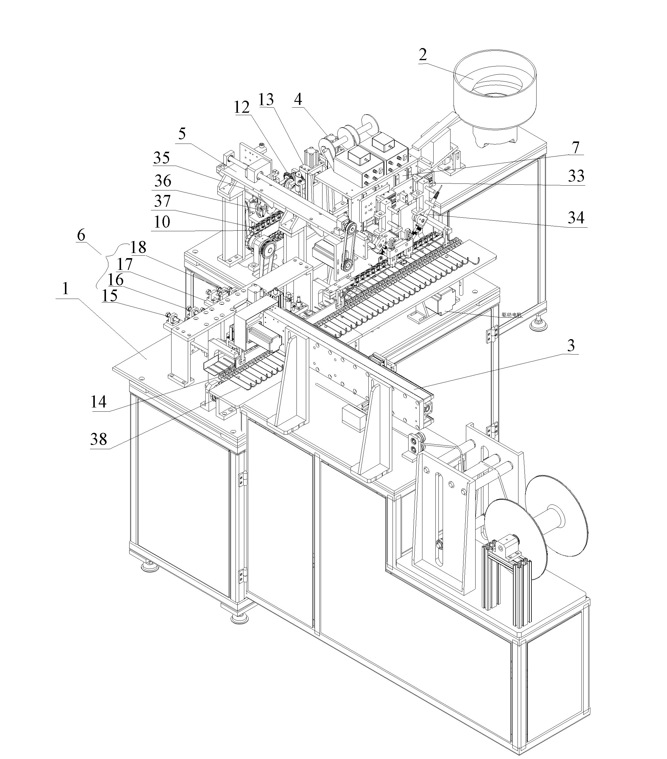
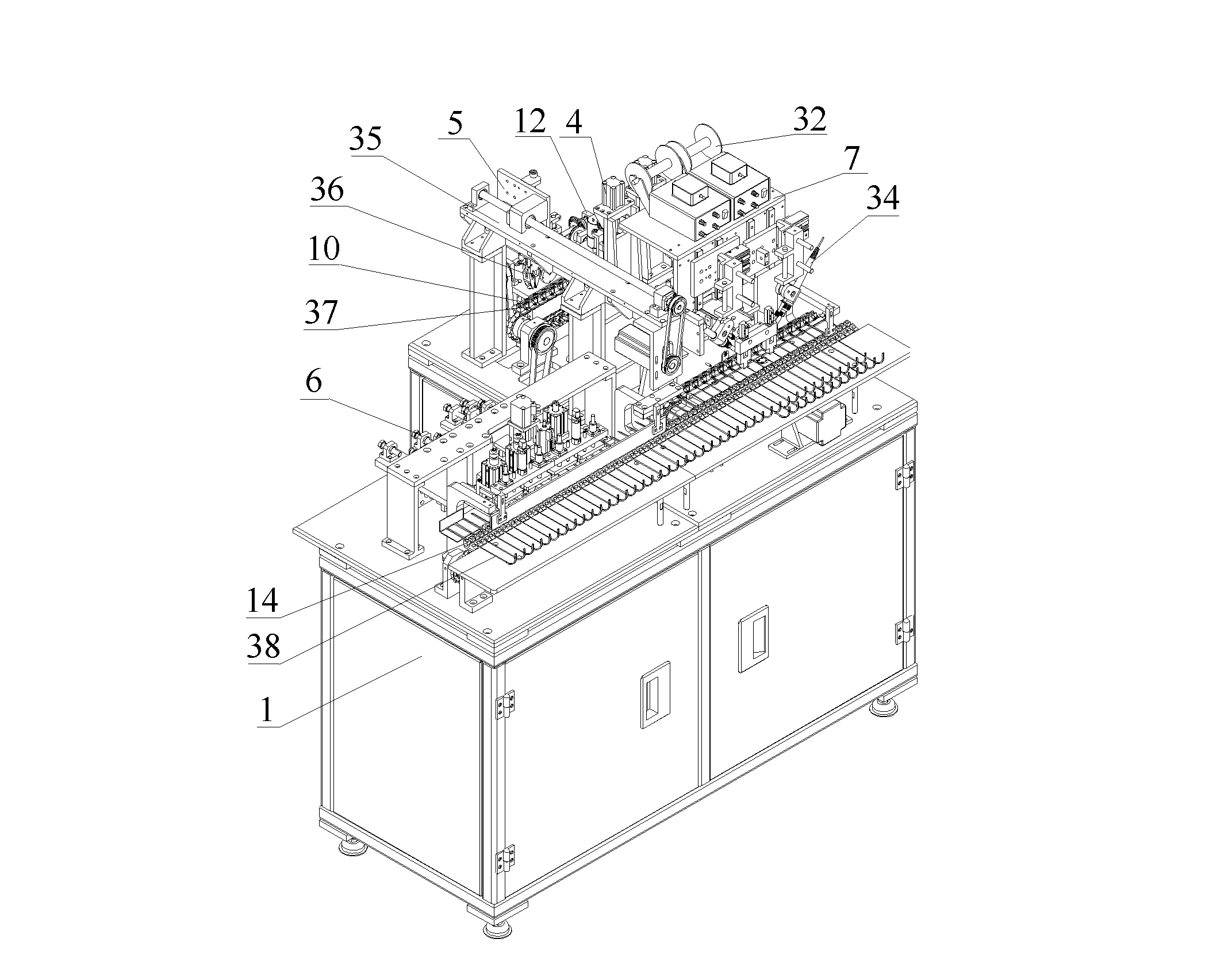
[0019] A DC power connector automatic welding machine, such as figure 1 with figure 2 As shown, it includes an automatic welding machine workbench 1, a joint vibration feeding mechanism 2 connected with the DC power supply joint automatic welding machine workbench 1, a cable pay-off mechanism 3 and its control mechanism. The DC power supply joint automatic welding machine is installed on the automatic The joint grinding mechanism 4 on the welding machine workbench 1, the joint translation mechanism 5, the cable branch line processing mechanism 6, and the joint welding mechanism 7 are composed.

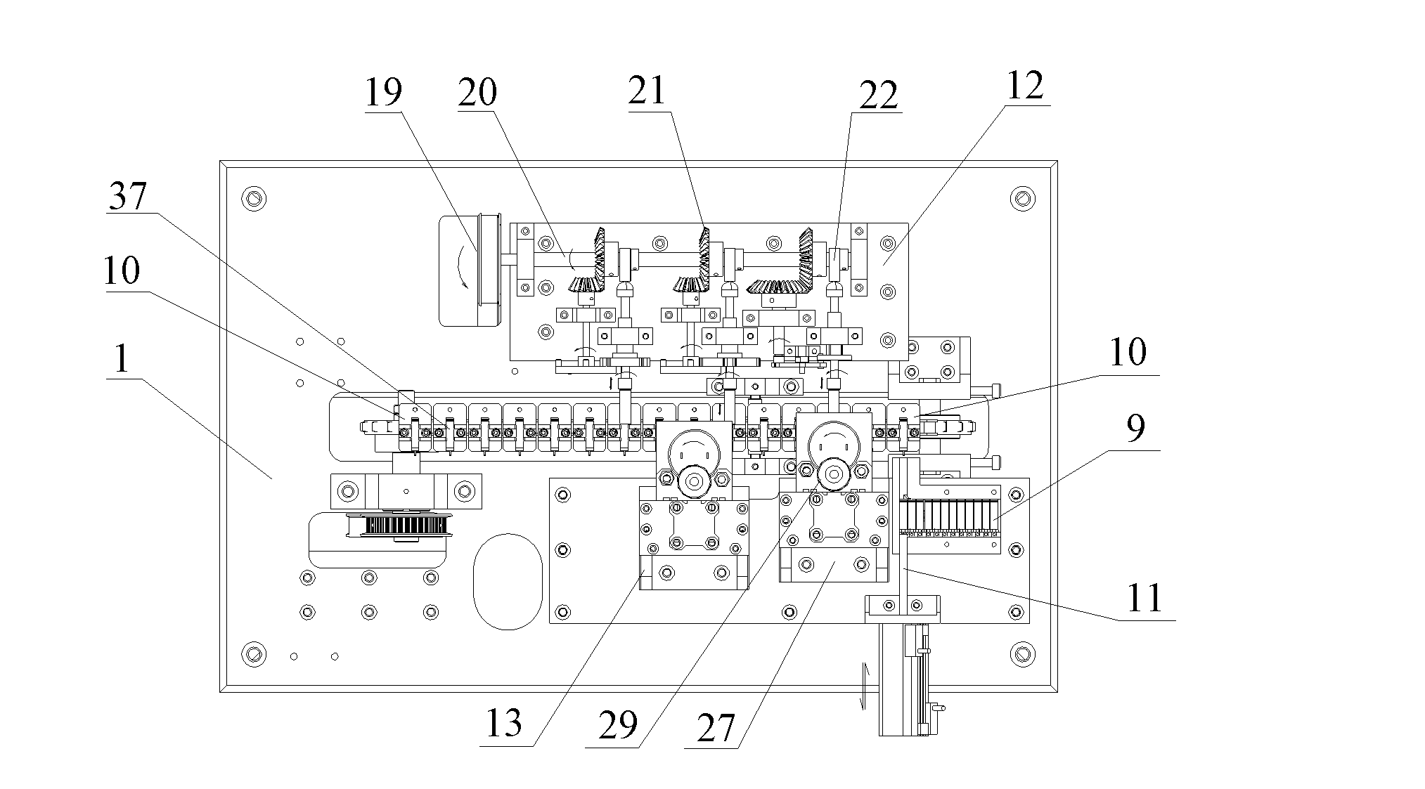
[0020] Joint grinding mechanism 4 of the present invention, such as image 3 , Figure 4 As shown, the pusher chute 9 provided by the joint feeding device 8 of the joint grinding processing mechanism 4 is connected with the outlet of the DC power ...


PUM


Abstract

The invention provides an automatic welding machine for a DC (direct-current) power supply connector. The automatic welding machine comprises an operating platform, a connector vibration feeding mechanism, a cable pay-off mechanism and a control mechanism of the cable pay-off mechanism, wherein the connector vibration feeding mechanism, the cable pay-off mechanism and the control mechanism of the cable pay-off mechanism are connected with the operating platform of the automatic welding machine for the DC power supply connector. The automatic welding machine further comprises a connecter grinding and processing mechanism, a connector translation mechanism, a cable separation processing mechanism and a connector welding mechanism which are arranged on the operating platform of the automatic welding machine. According to the automatic welding machine for the DC power supply connector provided by the invention, the DC power supply connector is ground by the connector grinding and processing mechanism on the operating platform of the automatic welding machine, the aligned separation, the stripping, peeling and the uniform cutting are carried out on the cables by the cable separation processing mechanism, and the DC power supply connector and cable bodies are welded by the connector welding mechanism so as to realize the automation of DC power supply connector welding. The automatic welding machine provided by the invention has high welding efficiency, and not only are the operating conditions improved, but also the processing efficiency and the product quality are improved.

Description

technical field [0001] The invention belongs to the technical field of electric appliance manufacturing, and relates to welding equipment for DC power supply joints, in particular to an automatic welding machine for DC power supply joints. Background technique [0002] The existing DC power connector is to weld two cable bodies with the outer skin peeled off at the end of the DC connector. Before welding, usually in order to improve the welding performance of the connector and the cable body, the DC power supply will be manually held. The joints are ground on a grinder, the grinding efficiency is not only low, but also the working environment is poor, a little carelessness is prone to work-related injuries; the cable body is also manually stripped on a simple wire stripping machine, the stripping efficiency is not high, and the operation Those who are also prone to fatigue. After the joints are polished, hand-held joints and stripped wires are used for manual welding. The w...

Claims


Application Information

Patent Timeline
Patent Type & Authority Applications(China)
IPC IPC(8): H01R43/00H01R43/02H01R43/28
Inventor 黄益文罗捷
Owner 东莞市双力数控设备有限公司
Why Eureka
Try Eureka