Microscopic flap lifting device used in LASIK (laser-assisted in situ keratomileusis) operation for femtosecond flap making
A femtosecond system and surgery technology, applied in the field of medical devices, can solve the problems of undiscovered patent documents, prone to micro-wrinkles, affecting postoperative vision, etc. Effect
- Summary
- Abstract
- Description
- Claims
- Application Information
AI Technical Summary
Problems solved by technology
Method used
Image


Examples
Embodiment 1
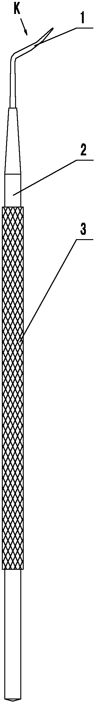
[0024] A micro flap lifter for femtosecond flap LASIK surgery, such as figure 1 , 2 As shown, it consists of a flap part 1 and a handle 2. The flap part is fixed on the upper end of the handle, and an anti-slip pattern 3 is formed on the hand-held part of the handle to prevent slippage of the instrument during the operation and make the operation safer.
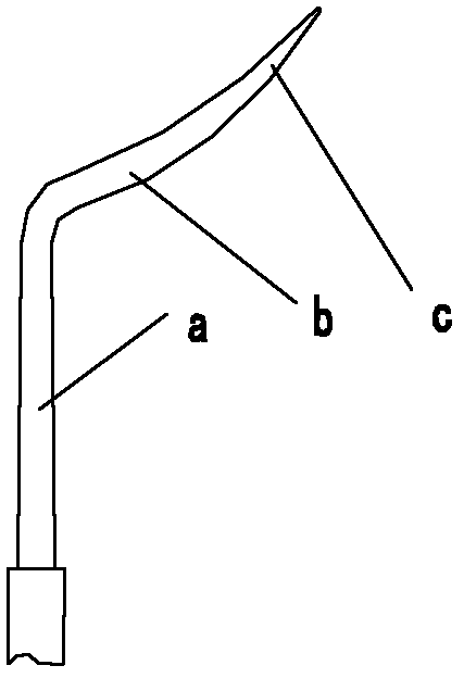
[0025] The structure of flap part is as image 3 , 4 , 5, the flap part is integrally connected by straight bar section a, arc section b and flat shovel section c, wherein the lower end of the straight bar section is coaxially fixed with the upper end of the handle, or is made in one body, and its horizontal The section is circular; with the extension of the upper part of the straight rod section, the diameter of the section becomes smaller gradually, and turns after about 1.5 cm, forming a circular arc section with an obtuse angle with the straight rod section. The cross section of the circular arc section is Flat ellipse...
Embodiment 2
[0030] A micro flap lifter for femtosecond flap LASIK surgery, see Figure 6 , 7 , 8, 9. Its external structure also includes a handle and a flap part, and the structure of the flap part in this embodiment is different from that in Embodiment 1. Only the structure of the flap portion is described below:
[0031] Such as Figure 6 As shown, the flap part includes a straight rod segment, an arc segment and a flat shovel segment, but there is also a turning segment d between the straight rod segment and the arc segment, and the turning segment and the straight rod segment are bent at an obtuse angle; The turning section and the arc section are reverse turning at an acute angle.
[0032] For the cross-sectional shapes of the straight bar section, between the turning section and the arc section, and the arc section, refer to Figure 9 , Figure 8 , Figure 7 .. The specific structure is described as follows:
[0033] The straight rod section is the direct continuation or f...
PUM
 Abstract
Description
Claims
Application Information