
Natural gas pipe corrosion inhibitor coating device

A technology for natural gas pipelines and film coating devices, which is applied to devices for coating liquid on surfaces, spray devices, liquid spray devices, etc., can solve problems such as difference in running speed, waste of corrosion inhibitor, and inability to fill two pigs with liquid. , to achieve the effect of reducing the cost of coating film and saving consumption

Inactive Publication Date: 2012-07-25
CHINA PETROCHEMICAL CORP +1
View PDF7 Cites 22 Cited by
  • Summary
  • Abstract
  • Description
  • Claims
  • Application Information

AI Technical Summary

Problems solved by technology

However, during the coating process of the two pigs in the pipeline, there is usually a difference in running speed during the walking process. If the speed of the front pig is greater than that of the rear pig, the liquid will not be able to fill the enclosed space of the two pigs. As a result, the upper tube wall cannot be exposed to the slow-release agent, which seriously affects the quality of the coating film
During the coating process, the slow-release agent sealed between the two pigs will also enter the bypass pipeline connected to the pipeline to be coated, resulting in a large waste of corrosion inhibitor

Method used


Image

  • Natural gas pipe corrosion inhibitor coating device
  • Natural gas pipe corrosion inhibitor coating device
  • Natural gas pipe corrosion inhibitor coating device

Examples


Embodiment Construction

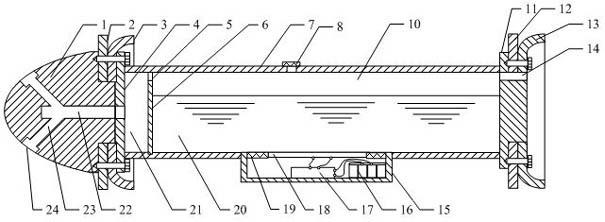
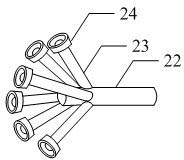
[0015] Depend on figure 1 and figure 2 It can be seen that the present invention consists of an atomizing head 1 and a tubular body 7. The atomizing head 1 is provided with an atomizing main channel 22 and an atomizing branch channel 23 communicating with it. The atomizing nozzle 24 is installed on the top of the atomizing branch channel 23. ; The front and rear ends of the tubular body 7 are respectively provided with a front cover 4 and a rear cover 11, the front cover 4 has a central hole communicating with the atomization main channel 22, and the rear cover 11 top is provided with an air-introduction through hole 14, the tubular A partition 6 is provided inside the body 7, and a ventilation hole 5 is provided on the top of the partition 6, and the tubular body 7 is divided into two chambers, a liquid storage chamber 10 and a premix chamber 21, and a corrosion inhibitor is provided above the liquid storage chamber 10. The filling port 8 is provided with an ultrasonic atom...


PUM


Abstract

The invention discloses a natural gas pipe corrosion inhibitor coating device, and particularly relates to a device for coating a corrosion inhibitor on a high-sulphur moisture collection and delivery pipe. The natural gas pipe corrosion inhibitor coating device comprises an atomizing head and a tubular body, a main atomizing channel, a secondary atomizing channel and atomizing nozzles of the secondary atomizing channel are arranged in the atomizing head, and the secondary atomizing channel is communicated with the main atomizing channel; a front cover plate and a rear cover plate are respectively arranged at the front end and the rear end of the tubular body, a center hole which is communicated with the main atomizing channel is arranged on the front cover plate, a gas leading through hole is arranged on the upper portion of the rear cover plate, a partition board is disposed in the tubular body, an air vent is arranged at the top of the partition board, the tubular body is divided into a liquid storage chamber and a pre-mixing chamber, a corrosion inhibitor filling opening is arranged on the upper side of the liquid storage chamber, and an ultrasonic atomizing chamber is arranged on the lower side of the liquid storage chamber; a guiding disc and a sealing cup are mounted between the atomizing head and the front cover plate of the tubular body and are connected via bolts; and another guiding disc and another sealing cup are mounted on the rear cover plate via bolts. The corrosion inhibitor is sprayed to the periphery of the pipe via the multiple atomizing nozzles, the shortcoming that a traditional coating device cannot coat the total periphery of a pipe is overcome, consumption of the corrosion inhibitor is reduced, and coating cost is lowered.

Description

technical field [0001] The invention discloses a corrosion inhibitor film coating device for natural gas pipelines, in particular to a corrosion inhibitor film coating device for high-sulfur moisture gas gathering and transportation pipelines. Background technique [0002] For sour gas pipelines containing hydrogen sulfide and dioxide, under the condition of effusion, it will cause serious electrochemical corrosion of the pipeline, resulting in thinning or even perforation of the pipe wall, resulting in the leakage of toxic media and causing poisoning, combustion, explosion and other accidents . In actual industrial production, regular injection of corrosion inhibitors into pipelines is usually used for coating to prevent pipeline corrosion. That is, the corrosion inhibitor is fully contacted with the inner wall of the pipe by using a film coating device, and the corrosion inhibitor is strongly combined with the metal surface inside the pipe through a special metal-friendly...

Claims


Application Information

Patent Timeline
Patent Type & Authority Applications(China)
IPC IPC(8): B05B17/06B05C7/02B05C7/08
CPCB05B13/0627B05B17/0615
Inventor 王寿平梁法春刘德旭龚金海陈婧燕慧
Owner CHINA PETROCHEMICAL CORP
Learn More