Die for preventing magnetic core from being cracked during sintering

A mold and magnetic core technology is applied in the field of molds to prevent sintering and cracking of magnetic cores.

Inactive Publication Date: 2012-07-25
上海康顺磁性元件厂有限公司 +1
View PDF0 Cites 0 Cited by
  • Summary
  • Abstract
  • Description
  • Claims
  • Application Information

AI Technical Summary

Problems solved by technology

Furthermore, after the adhesive volatilizes, the uneven shrinkage of the blank will also lead to cracking due to the rapid heating rate.

Method used


Image

  • Die for preventing magnetic core from being cracked during sintering
  • Die for preventing magnetic core from being cracked during sintering
  • Die for preventing magnetic core from being cracked during sintering

Examples


Embodiment 1

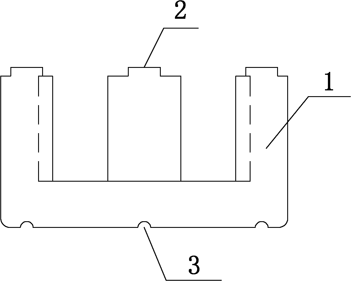
[0017] The mold to prevent the sintering and cracking of the magnetic core has a structure such as figure 1 As shown, the mold 1 is an E-shaped structure with a horizontal opening upwards, the inner side of the protruding parts at the left and right ends is an arc-shaped structure, and the middle protruding part is a cylindrical structure, which is set on the inner side of the top of the cylindrical structure and the top inner side of the left and right ends. A convex surface 2, the length of the convex surface 2 is 8mm, the width is 4mm, and the height is 0.5mm. The inner surface of the bottom of the mold 1 is provided with a concave point 3, the diameter of the concave point is 5mm, and the depth is 1mm.

Embodiment 2

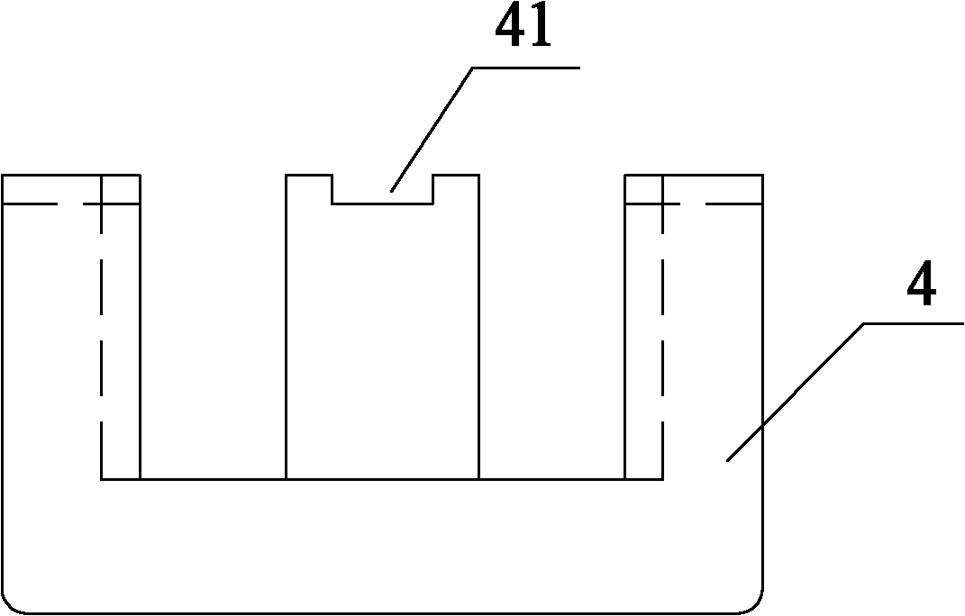
[0019] A mold for preventing sintering and cracking of the magnetic core. The mold is an E-shaped structure with a lateral opening upwards. The inner sides of the protruding parts at the left and right ends are arc-shaped structures, and the middle protruding part is a cylindrical structure. The convexity has a length of 5 mm, a width of 3 mm and a height of 0.3 mm. The magnetic core 4 fired by this mold is as Figure 2~3 As shown, the larger magnetic core 4 is easy to crack during sintering, and sometimes there is an internal pond core. In view of this situation, when designing the mold, the lower punch is made with a length of 5mm and a width of 3mm (taken according to the actual size of the product) different values), a convex surface with a height of 0.3mm, the surface of the blank of the formed magnetic core 4 will form a concave exhaust groove 41 with a length of 5mm, a width of 3mm, and a depth of 0.3mm. An exhaust channel is created, which is conducive to the drainage...

Embodiment 3

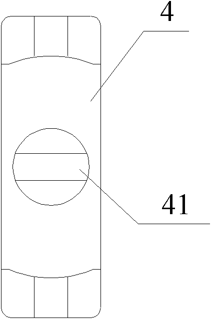
[0021] The mold to prevent the sintering and cracking of the magnetic core. The mold is an E-shaped structure with a lateral opening upwards. The inner side of the left and right protruding parts is an arc-shaped structure, and the middle protruding part is a cylindrical structure. There are three concave points on the inner surface of the bottom of the mold. The pit diameter is 3 mm and the depth is 0.5 mm. The magnetic core 4 fired by this mold is as Figure 4 As shown, the molded blank will be in contact with the sintered carrier (setter or push plate) during sintering, and sometimes cracks (mainly cracks) and crystal points of the bottom plate of the magnetic core 4 will occur. Usually, zirconium plates are placed or corundum or alumina powder is sprinkled to prevent the magnetic core from contacting the setter or push plate, but this operation will increase the production cost. In view of this situation, when designing the mold, a concave point with a diameter of 3mm and...


PUM

PropertyMeasurementUnit
lengthaaaaaaaaaa
widthaaaaaaaaaa
heightaaaaaaaaaa

Abstract

The invention relates to a die for preventing a magnetic core from being cracked during sintering. The die is in a transverse E-shaped structure; the inner sides of projection parts at the left and right ends are in arc structures, and a projection part in the middle is in a column structure. Compared with the prior art, the die of the magnetic core is improved under the condition that the structure, the shape size and the performance of the magnetic core totally meet the requirements according to the invention; the problem caused by the fact that the loading capacity is large or a few gaps exist between blanks is overcome; enough space is provided to discharge water and rubber when the magnetic core is sintered; water and rubber discharge is facilitated, and the cracking problem of the magnetic core during sintering is solved.

Description

technical field [0001] The invention relates to a magnetic core firing mold, in particular to a mold for preventing the magnetic core from sintering and cracking. Background technique [0002] The soft ferrite core is molded by material powder and sintered at high temperature. Since the soft ferrite particles are not plastic, auxiliary materials must be added to complete the molding. The commonly used auxiliary material is PVA (polyvinyl alcohol, customary called adhesive). During the sintering process, when the temperature of the blank or a certain part of the blank rises to the corresponding temperature, that is, when the temperature reaches the boiling point of water or the volatilization or decomposition point of PVA, the water and PVA contained in the blank will be reduced. A large amount will be volatilized, and this process is customarily called "degumming". If drainage and debinding are difficult due to various factors, the sintered blank will crack. For the probl...

Claims


Application Information

Patent Timeline
Patent Type & Authority Applications(China)
IPC IPC(8): B22F3/14
Inventor 沈永春陈俊龙彬熊小东
Owner 上海康顺磁性元件厂有限公司
Why Eureka
Try Eureka