Driving mechanism for die-assembling thrust base

A transmission mechanism and thrust seat technology, which is applied in the field of mold clamping parts of injection molding machines, can solve problems such as high energy consumption, difficult maintenance, and high noise, and achieve the effects of low energy consumption, small space occupation, and strong bearing capacity

Inactive Publication Date: 2014-07-16
ZHEJIANG UNIV
View PDF5 Cites 0 Cited by
  • Summary
  • Abstract
  • Description
  • Claims
  • Application Information

AI Technical Summary

Problems solved by technology

[0003] The purpose of the present invention is to provide a transmission mechanism for the mold clamping thrust seat in view of the defects of the traditional hydraulic drive system such as high noise, difficult maintenance and high energy consumption

Method used


Image

  • Driving mechanism for die-assembling thrust base
  • Driving mechanism for die-assembling thrust base
  • Driving mechanism for die-assembling thrust base

Examples


Embodiment Construction

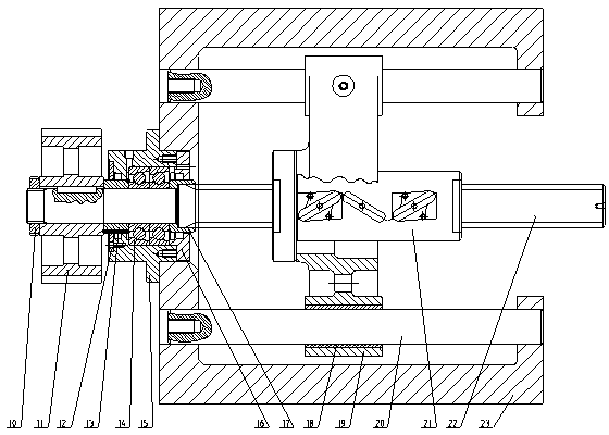
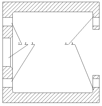
[0014] Such as figure 1 As shown, the tail plate 23 is composed of the rear wall surface and the left tail plate bracket 4 and the right tail plate bracket 5 fixed on the rear wall surface. There is a hole 1 on the left side of the tail plate and two holes 3 on the right side of the tail plate. There is a support hole coaxial with the hole 1 on the left side of the tail plate on the left bracket 4 of the tail plate. Hole 3 is coaxial with the support hole. The axis of the hole 1 on the left side of the tail plate, the axis of the hole 3 on the right side of the tail plate and the axis of the center hole 2 are parallel and in the same plane.

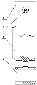
[0015] Such as figure 2 As shown, the center of the thrust seat 19 is the center hole 8 of the thrust seat, and the two sides of the center hole 8 of the thrust seat are symmetrically distributed with the left hole 6 of the thrust seat and the right hole 9 of the thrust seat, and the left hole 6 of the thrust seat and the right side of...


PUM


Abstract

The invention discloses a driving mechanism for a die-assembling thrust base, which comprises two guide rods and a ball screw, wherein the guide rods and the ball screw are arranged on a tail plate, and a ball nut is arranged on the center hole of the thrust base; holes at two sides of the thrust base are internally provided with a copper sleeve respectively, and the copper sleeves are respectively sleeved on the two guide rods, and can slide along with the guide rods; a servo motor is taken as the power moving the thrust base, the running of a motor is transmitted to the ball screw by a synchronous toothed belt and a belt wheel, the ball screw only can move along with a linear line, and can move along with the axes of the guide rods along with the thrust base, and a movable template is driven by a dynamic-belt dynamic-toggle rod mechanism, so that the die can be disassembled and assembled, and die locking force can be provided. The whole driving mechanism for the die-assembling thrust base is compact in structure, high in intensity, high in carrying capacity, stable to run, driven by the servo motor and a ball screw assembly, quick to move, and exact to control, so that the defects of large noise, difficulty in maintenance, high energy consumption, and the like of the driving mechanism for the die-assembling thrust base can be overcome.

Description

technical field [0001] The invention relates to a mold clamping part of an injection molding machine, in particular to a transmission mechanism of a mold clamping thrust seat. Background technique [0002] In the mold clamping part of the injection molding machine, the forward and backward movement of the thrust seat is amplified by the force of the toggle mechanism to obtain the opening and closing action of the movable template. However, the traditional hydraulic drive system is difficult to maintain its characteristics after continuous operation and oil temperature changes, and the control accuracy is affected. Moreover, the hydraulic system is noisy, difficult to maintain, and high in energy consumption. Contents of the invention [0003] The purpose of the present invention is to provide a transmission mechanism of the mold clamping thrust seat for the defects of the traditional hydraulic drive system such as high noise, difficult maintenance and high energy consumpti...

Claims


Application Information

Patent Timeline
Patent Type & Authority Patents(China)
IPC IPC(8): B29C45/66
Inventor 李凌丰茅旭飞张振然管灵波
Owner ZHEJIANG UNIV
Why Eureka
Try Eureka