Motor rotating shaft with spoke iron plates

A motor shaft and spoke iron technology, which is applied in the field of motor shafts with spoke irons, can solve problems such as broken shafts, no fundamental improvement in motor rotor ventilation, and large stress on spoke irons, and achieve low cost, poor ventilation, and processing and installation convenient effect

Inactive Publication Date: 2012-07-25
ELECTRIC POWER RES INST STATE GRID SHANXI ELECTRIC POWER +1
View PDF3 Cites 3 Cited by
  • Summary
  • Abstract
  • Description
  • Claims
  • Application Information

AI Technical Summary

Problems solved by technology

[0003] The motor shaft with spoke irons provided by the present invention solves the problem that the existing motor shafts with spoke irons have a large stress on the cross section of the spoke irons perpendicular to the shaft , it is easy to cause shaft breakage and technical problems that the internal ventilation of the motor rotor has not been fundamentally improved

Method used


Image

  • Motor rotating shaft with spoke iron plates
  • Motor rotating shaft with spoke iron plates
  • Motor rotating shaft with spoke iron plates

Examples


Embodiment Construction

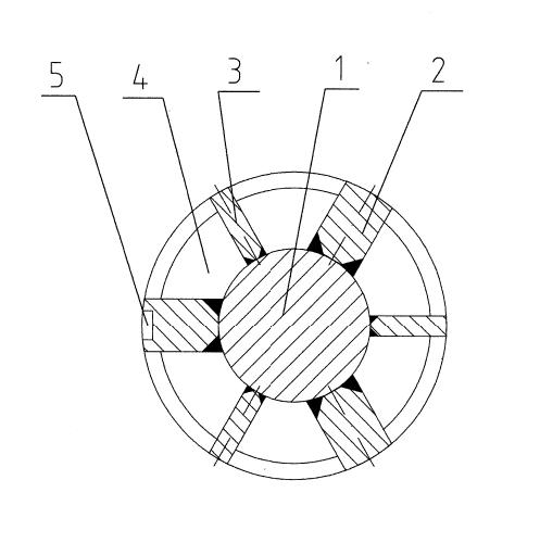
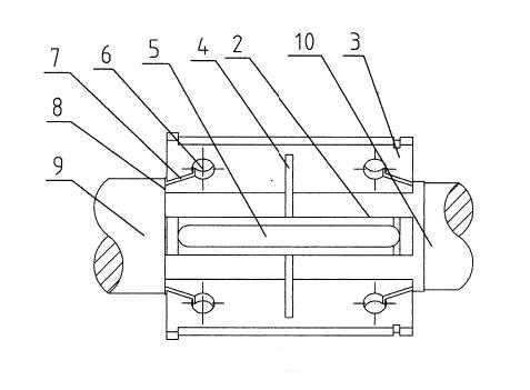
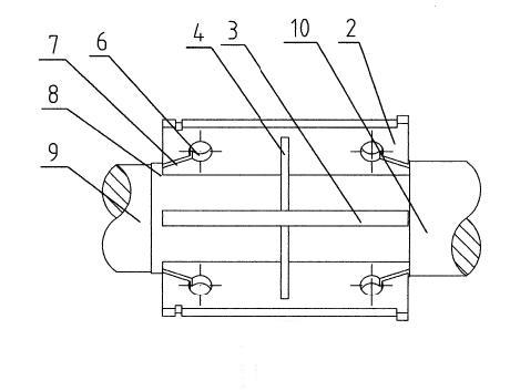
[0013] A motor rotating shaft with spoke iron, comprising a shaft 1, a wide-spoke iron plate 2, a narrow-spoke iron plate 3, a fan-shaped air blocking plate 4 and a keyway 5 arranged on a wide-spoke iron plate 2, the wide-spoke iron Both the plate 2 and the narrow-spoke iron plate 3 are fixedly arranged on the outer surface of the shaft 1 along the axial direction of the shaft 1, and the wide-spoke iron plates arranged on the outer surface of the shaft 1 are arranged on the circumference of the section perpendicular to the axis of the shaft 1. Evenly and equidistantly arranged, the narrow-radius iron plates arranged on the side of the shaft 1 are also arranged at uniform and equidistant intervals on the circumference of the cross-section perpendicular to the axis of the shaft 1, and the narrow-radius iron plates arranged on the side of the shaft 1 and The wide-radiated iron plates are arranged at intervals, and the distance from each wide-radiated iron plate to the left and rig...


PUM


Abstract

The invention discloses a motor rotating shaft with spoke iron plates, which solves the technical problems that the stress of the cross sections of spoke iron plates perpendicular to a shaft is large, and the shaft is easy to break in an existing motor rotating shaft with spoke iron plates. The motor rotating shaft comprises a shaft (1), the wide spoke iron plate, the narrow spoke iron plate and a fan-shaped air blocking plate (4), both the wide spoke iron plate (2) and the narrow spoke iron plate (3) are fixedly arranged on the shaft (1) along the direction of the shaft (1) and are evenly and equidistantly spaced, and a cylindrical unloading through hole (6) and an unloading groove (7) are symmetrically arranged on each of the wide spoke iron plate and the narrow spoke iron plate. The motor rotating shaft has the advantages of simple structure, low cost and convenience in processing and installation.

Description

technical field [0001] The invention relates to a motor shaft, in particular to a motor shaft with spoke irons. Background technique [0002] The existing motor shaft is generally composed of the shaft and the rotor core fixed on it. Because the entire rotor is a solid core structure, the mass of the rotor is large, and the axial flexibility changes greatly during the rotation of the rotor. At the same time, there is a motor The problem of poor heat dissipation of the rotor. In order to solve the above problems, a motor shaft with spoke iron appeared. At this time, the motor shaft is composed of a shaft and a spoke iron plate, thereby reducing the mass of the rotor. However, the motor shaft with this structure has spokes. The stress on the cross-section perpendicular to the shaft of the iron is large, which is likely to cause the problem of shaft fracture. At the same time, the motor with this structure only solves the axial ventilation of the motor rotor, but does not sol...

Claims


Application Information

Patent Timeline
IPC IPC(8): F16C3/02
Inventor 仇汴万学治冯爱香杨华王红卫王浩王健宋述停王强
Owner ELECTRIC POWER RES INST STATE GRID SHANXI ELECTRIC POWER
Why Eureka
Try Eureka