Optical freeform surface interference detection system

An interference detection, free technology, applied in the direction of using optical devices, measuring devices, instruments, etc., can solve the problems of slow measurement methods, many error sources, unfavorable detection accuracy, etc., to overcome singleness and high cost, overcome large errors, Overcome the effect of high displacement accuracy requirements

Inactive Publication Date: 2012-07-25
NANJING UNIV OF SCI & TECH
View PDF5 Cites 35 Cited by
  • Summary
  • Abstract
  • Description
  • Claims
  • Application Information

AI Technical Summary

Problems solved by technology

Generally, the first and second stages use a three-coordinate machine and a surface profiler for inspection respectively. The third stage requires the highest precision. The polished optical free-form surface must take into account the ultra-high precision requirements for measurement and the inspection process. The contradiction between measurement accuracy and measurement range makes traditional contact measurement unable to meet the requirements
At present, different methods have been proposed for optical free-form surface detection technology at home and abroad, but there are problems: the measurement method is slow and the flexibility is not enough
This scheme can detect both rotationally symmetric aspheric surfaces and non-rotationally symmetric aspheric surfaces, and has the application prospect of detecting free-form surfaces. However, the interferometric system uses an improved Tieman Green type, and many optical elements are introduced into the interferometer reference arm. The optical path is complicated. , there are many error sources, which is not conducive to improving the detection accuracy

Method used


Image

  • Optical freeform surface interference detection system
  • Optical freeform surface interference detection system
  • Optical freeform surface interference detection system

Examples


Embodiment Construction

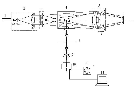
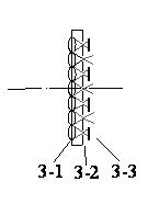
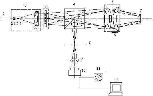
[0009] The optical free-form surface interference detection device of the present invention includes a laser 1, a beam expander system 2, a controllable microlens point source array 3, a beam splitting prism 4, a standard spherical lens group 5, a phase shifter 6, an aperture diaphragm 8, and an imaging lens 9. Charge coupled device CCD1, monitor 11 and computer 12; controllable microlens point source array 3 includes microlens array 3-1, pinhole array 3-2 and light source selection mask plate 3-3, controllable microlens The point source array 3 is located on the outgoing light path of the laser, and is used to generate the selected point light source. The microlens array 3-1 is followed by the pinhole array 3-2, and the light source selection mask plate 3-3 is placed behind the pinhole array 3-2; the array number of the microlens array 3-1, the pinhole array 3 The number of arrays of -2 and the number of arrays of the light source selection mask plate 3-3 are the same.

[00...


PUM


Abstract

The invention discloses an optical freeform surface interference detection system. A point light source array is adopted to generate a multi-field-of-view sloped wavefront to illuminate a measured optical freeform surface, the point light sources located on the optical axis are always lit up as reference light, and according to the phase-shifting interferometry, subregion wavefront data are recovered from a multi-field-of-view interferogram; a standard spherical surface is used for calibrating the positional relation between CCD (Charge Coupled Device) pixels and the multi-field-of-view interferogram, the position of the multi-field-of-view interferogram is shifted when the optical freeform surface is measured, and wavefront slope information is obtained from the offset; and according to the slope information and multi-field-of-view subregion wavefront data, the surface form information of the measured surface is reconstructed. A controllable point light source array-lighting scheme is generated according to the characteristics of the measured surface, and the system can cover a variety of test objects (convex-concave aspheric surfaces and freeform surfaces). The invention overcomes the defects of simplicity and high cost of the conventional freeform surface detection method, the defect of great error caused by the non-common path in the conventional detection method and the defect of high displacement precision requirement of the subaperture method.

Description

technical field [0001] The invention relates to a Fizeau-type common optical path interference measurement device, in particular to a device used for surface quality inspection of optical aspheric surfaces and optical free-form surfaces. Background technique [0002] In recent years, the superiority of optical free-form surfaces has attracted widespread attention of scientific and technical personnel, and they have tried to use free-form surfaces to improve the performance of optical systems. It is generally believed that optical free-form surfaces will have a revolutionary impact on the quality and miniaturization of optical systems, but no matter Neither the production cost nor the processing accuracy can compare with the traditional aspheric surface. The precise detection of surface shape is the bottleneck technology restricting the development of free-form surface technology. [0003] The processing of optical free-form surfaces is divided into three stages: milling, gri...

Claims


Application Information

Patent Timeline
Patent Type & Authority Applications(China)
IPC IPC(8): G01B11/24G01B9/02
Inventor 高志山倪江楠袁群
Owner NANJING UNIV OF SCI & TECH
Why Eureka
Try Eureka