
Rubber coating mechanism of high-speed automatic coil winding machine

An automatic winding machine, high-speed technology, applied in the direction of coil manufacturing, etc., can solve the problems of high cost, unfavorable mass production, and complex structure of the rubber-covered structure, and achieve simple structure, good economic effect and effect, and reduce the cost of the mechanism Effect

Active Publication Date: 2012-07-25
深圳市泰顺友电机电有限公司
View PDF6 Cites 8 Cited by
  • Summary
  • Abstract
  • Description
  • Claims
  • Application Information

AI Technical Summary

Problems solved by technology

[0004] Although the encapsulation mechanism of the above structure can realize the encapsulation function, its structure is complicated. In particular, this encapsulation mechanism uses a large number of cylinders, especially in The cost of adopting multiple sets of such structure of the lagging structure is very high and it is not conducive to mass production

Method used


Image

  • Rubber coating mechanism of high-speed automatic coil winding machine
  • Rubber coating mechanism of high-speed automatic coil winding machine
  • Rubber coating mechanism of high-speed automatic coil winding machine

Examples


Embodiment Construction

[0023] In order to make the objectives, technical solutions and advantages of the present invention clearer, the present invention will be further described in detail below with reference to the accompanying drawings and embodiments. It should be understood that the specific embodiments described herein are only used to explain the present invention, but not to limit the present invention.

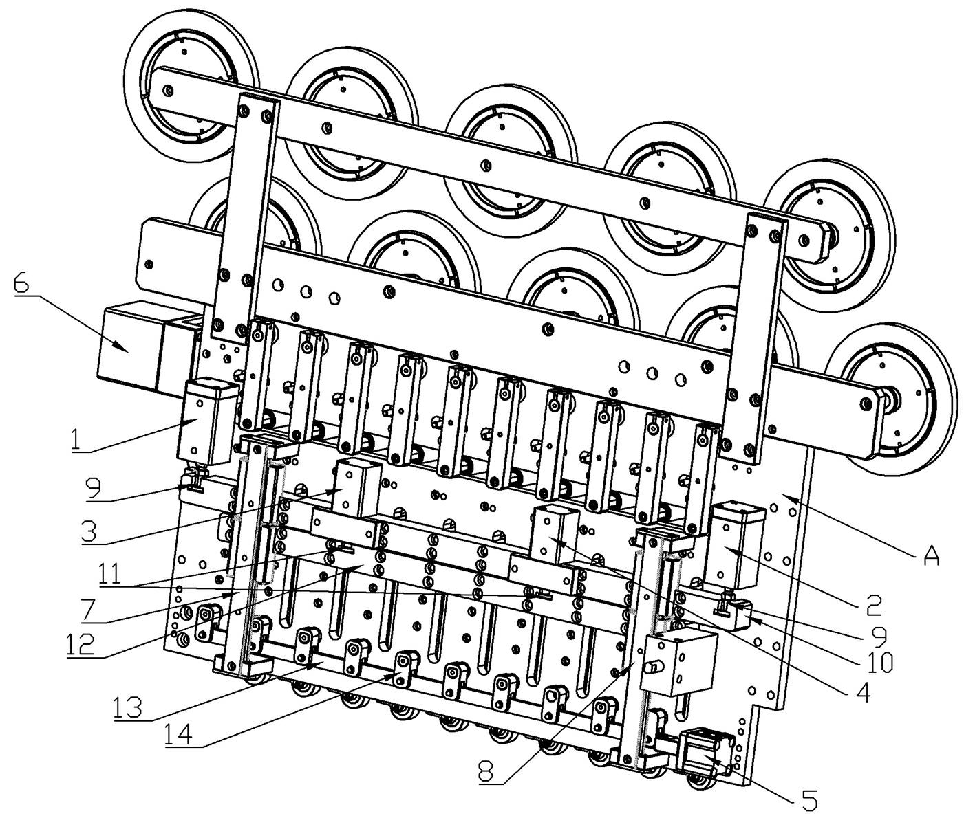
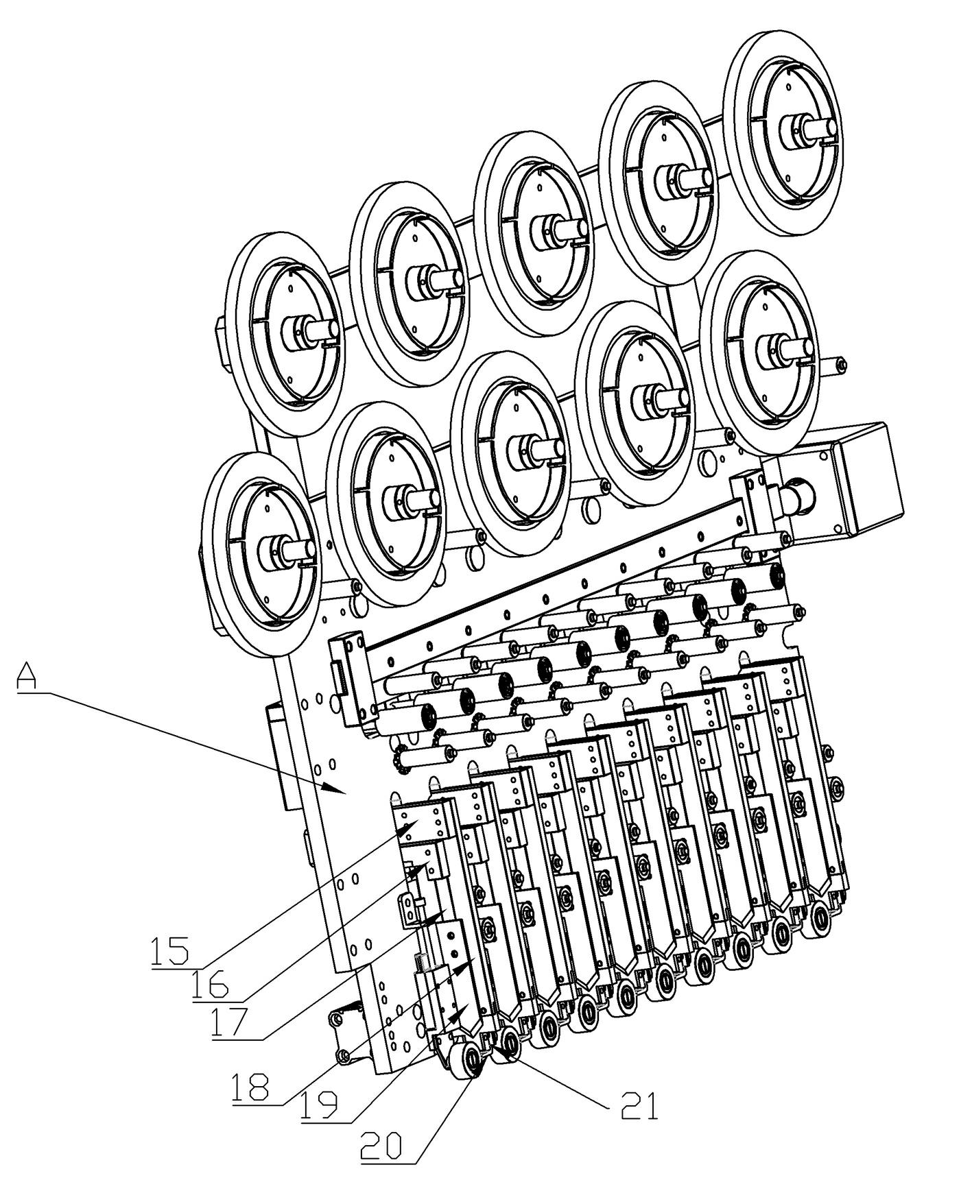
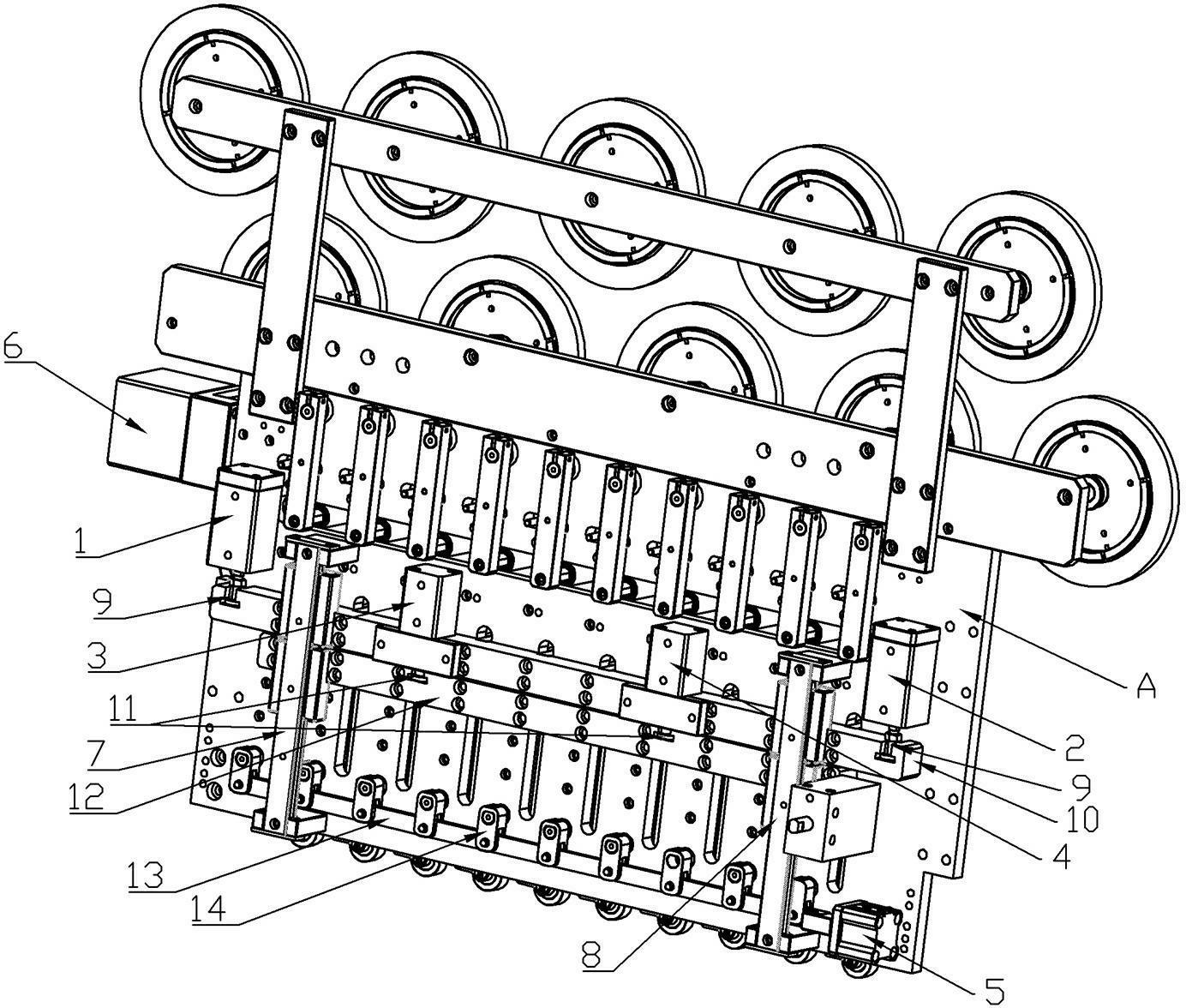
[0024] see Figure 1 to Figure 2 , the present invention is a high-speed automatic winding machine wrapping mechanism, which mainly includes:

[0025] The vertical plate connected with the main engine through the connecting piece, the first cylinder 1 and the second cylinder 2 fixed on the vertical plate A, the first cylinder joint 9 connected with the first cylinder 1 and the second cylinder 2 respectively, and The first cross arm 10 connected to the first cylinder joint 9 is a linear slide rail that is fixedly arranged on the vertical plate A and is slidably matched with the first c...


PUM


Abstract

The invention provides a rubber coating mechanism of a high-speed automatic coil winding machine, which mainly comprises a vertical plate, a first cylinder, a second cylinder, a first cylinder connector respectively connected with the first cylinder and the second cylinder, a first cross arm, a linear sliding rail in sliding match with the first cross arm, a first connecting block arranged on thefirst cross arm, a guide groove fixing block, a tackless positioning plate connected onto the guide groove fixing block, a third cylinder, a fourth cylinder, a second cylinder connector respectively connected with the third cylinder and the fourth cylinder, a second cross arm connected with the second cylinder connector, a second connecting block, a cutter shifting block, a cutter locked on the cutter shifting block, a fifth cylinder arranged on the vertical plate, a connecting strip arranged at the shaft outlet end of the fifth cylinder, a pressed rotating block arranged on the connecting strip, and a pressing block arranged on the pressed rotating block, wherein the first cylinder and the second cylinder are fixed on the vertical plate, and the second connecting block and the cutter shifting block are arranged on the second cross arm. The rubber coating mechanism is simple in structure, adopts few pneumatic elements and can still achieve processing precision.

Description

technical field [0001] The invention relates to the technical field of high-speed automatic winding machines, in particular to a rubber covering mechanism used for the rubber covering operation of winding machines such as electronic transformers and electromagnetic coils. Background technique [0002] Due to the development of the modern electronic industry, processes such as winding, wrapping, welding, and tin immersion in the processing of electronic components are often used on one device at the same time; therefore, high-speed winding machines with wrapping mechanisms are produced. [0003] Such as the Chinese utility model patent, the publication number is: CN201796724U, and the patent name is: "a cutter group of a winding rubber cloth machine" patent discloses a cutting knife group of a winding rubber cloth machine: "It is characterized in that: The cutter group includes a base plate slidingly connected with the base plate; the base plate is fixed with a first cylinder...

Claims


Application Information

Patent Timeline
Patent Type & Authority Applications(China)
IPC IPC(8): H01F41/12B65H81/00
Inventor 范安成
Owner 深圳市泰顺友电机电有限公司
Learn More