Capacitor switching device

A capacitor switching and switching technology, applied in reactive power compensation, reactive power adjustment/elimination/compensation, etc., can solve the problem of load capacitance and capacitive switching, unfavorable service life and reliability, large dispersion of photoelectric transmission efficiency, The problem of high energy consumption of the current limiting resistor, etc., achieves the effects of good consistency, strong anti-interference ability, and accurate voltage zero-crossing input.

Inactive Publication Date: 2012-07-25
GUANGZHOU JINSHI ELECTRONICS
View PDF5 Cites 2 Cited by
  • Summary
  • Abstract
  • Description
  • Claims
  • Application Information

AI Technical Summary

Problems solved by technology

[0002] At present, in power compensation systems, capacitive switching switches such as thyristors and synchronous switches are widely used to switch capacitors. Zero accuracy, which requires the voltage zero-crossing detection circuit at both ends of the main circuit switch to detect accurately and have strong anti-interference ability. At present, the input terminal of the photocoupler is connected in series with the current limiting resistor, and the output terminal outputs the voltage zero-crossing signal. The control circuit controls the switch voltage of the main circuit switch to turn on at zero crossing, but the photocoupler has the disadvantages of large drive current and large dispersion of photoelectric transmission efficiency. The voltage superposition and the DC voltage component cause the current limiting resistor to consume a lot of energy. For example, the energy consumption and heat generation of the capacitor switching switch will be greater in frequent switching operations. In order to take into account the acceptable energy consumption, most of the current capacitors The zero-crossing detection accuracy of the switching switch voltage is about plus or minus 50V, which will also generate a large surge current, which will adversely affect the service life and reliability of the load capacitor and the capacitor switching switch itself.

Method used


Image

  • Capacitor switching device
  • Capacitor switching device
  • Capacitor switching device

Examples


Embodiment Construction

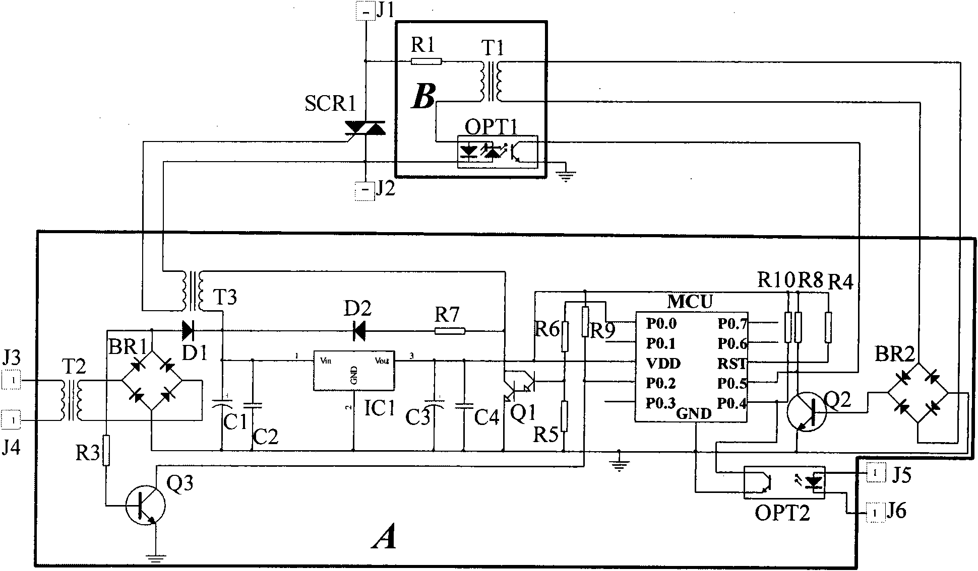
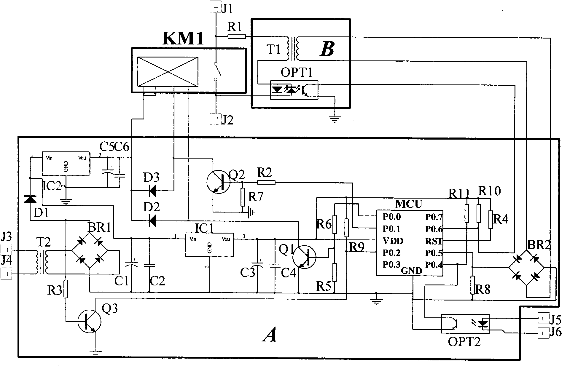
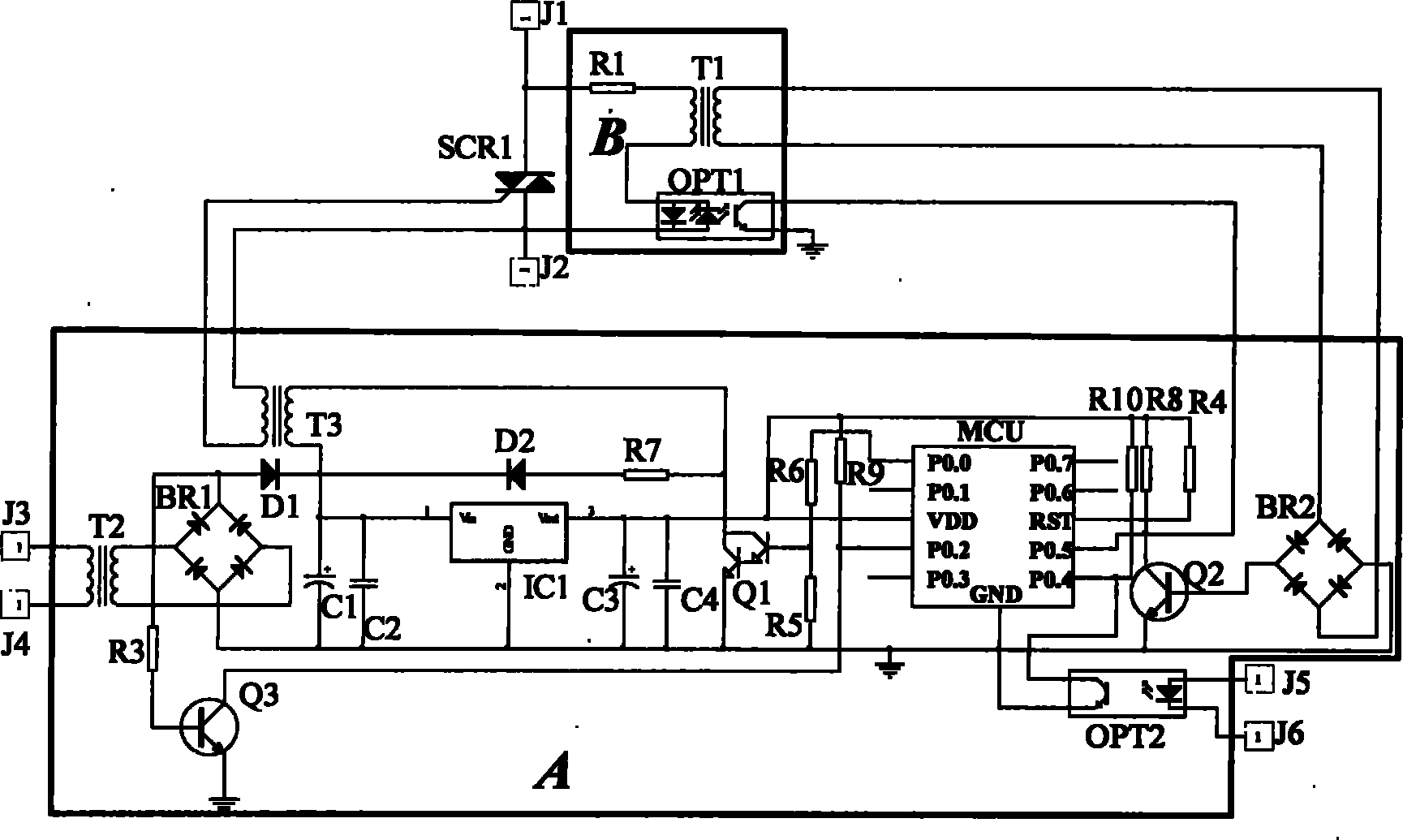
[0021] as attached figure 1 The main circuit switch of the capacitor switching switch shown is a thyristor, the voltage zero-crossing detection circuit B is connected to the input and output terminals of the thyristor SCR1, and J1 and J2 are respectively the input and output terminals of the main circuit switch thyristor SCR1, The conduction control end of the thyristor SCR1 is connected to the control circuit A, J3 and J4 are the power input ends of the control circuit A, and J5 and J6 are the control signal input ends for controlling the input of the capacitor switching switch.

[0022] Voltage zero-crossing detection circuit B: The input terminal of the photocoupler OPT1 is connected in series with the input terminal of the transformer T1, and then connected to the input and output terminals of the thyristor SCR1 through the current limiting resistor R1, the output terminal of the photocoupler OPT1 and the output terminal of the transformer T1 Connect to control circuit A. ...


PUM


Abstract

The invention discloses a capacitor switching device, which belongs to the field of electric switches, and particularly relates to the capacitor switching device which can carry out accurate voltage zero-crossing input and has high reliability. The capacitor switching device adopts a voltage zero-crossing detection circuit consisting of a photoelectric coupler and a mutual inductor in a double-voltage zero-crossing sampling mode, and combines the advantages of the mutual inductor of high flexibility and good consistency with the advantages of the photoelectric coupler of small distribution capacitance of an input end relative to an output end and strong antijamming capacity, so the photoelectric coupler and the mutual inductor complement each other, a control circuit utilizes two signals which are respectively outputted by the photoelectric coupler and the mutual inductor as the voltage zero passage signals, so the capacitor switching device has the characteristics of accurate voltage zero-crossing input, small inrush current, strong antijamming capacity, low energy consumption of the voltage zero-crossing detection circuit, long electric service life and high reliability, and is more suitable for being used on the occasion that the capacitor is required to be frequently switched.

Description

technical field [0001] The capacitor switching switch of the invention belongs to the field of electric switches, in particular to a capacitor switching switch capable of accurate voltage zero-crossing input and high reliability. Background technique [0002] At present, in power compensation systems, capacitive switching switches such as thyristors and synchronous switches are widely used to switch capacitors. Zero accuracy, which requires the voltage zero-crossing detection circuit at both ends of the main circuit switch to detect accurately and have strong anti-interference ability. At present, the input terminal of the photocoupler is connected in series with the current limiting resistor, and the output terminal outputs the voltage zero-crossing signal. The control circuit controls the switch voltage of the main circuit switch to turn on at zero crossing, but the photocoupler has the disadvantages of large drive current and large dispersion of photoelectric transmission...

Claims


Application Information

Patent Timeline
Patent Type & Authority Applications(China)
IPC IPC(8): H02J3/18
CPCY02E40/30
Inventor 郭桥石
Owner GUANGZHOU JINSHI ELECTRONICS
Why Eureka
Try Eureka