
Power factor monitoring and compensating system

A power factor and compensation system technology, applied in reactive power compensation, reactive power adjustment/elimination/compensation, electric power measurement through current/voltage, etc. , to achieve the effect of simple circuit structure, high measurement accuracy and strong independent working ability

Inactive Publication Date: 2012-07-25
LUDONG UNIVERSITY
View PDF3 Cites 18 Cited by
  • Summary
  • Abstract
  • Description
  • Claims
  • Application Information

AI Technical Summary

Problems solved by technology

Its disadvantage is that it does not select the appropriate microprocessor 1 chip and capacitor switching control chip, resulting in more complex peripheral circuits, and the lower computer has no visual human-machine interface, and the upper computer is required for parameter setting and basic control, making distributed applications are limited, and also greatly increase the cost of the product

Method used


Image

  • Power factor monitoring and compensating system
  • Power factor monitoring and compensating system
  • Power factor monitoring and compensating system

Examples


Embodiment Construction

[0014] The present invention will be further described below in conjunction with the accompanying drawings.

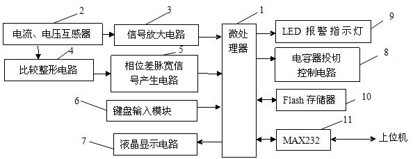
[0015] exist figure 1 , it can be seen that the lower computer of the power factor monitoring and compensation system is mainly composed of a microprocessor 1, a current and voltage transformer 2, a signal amplification circuit 3, a comparison shaping circuit 4, a phase difference pulse width signal generation circuit 5, a keyboard input module 6, The liquid crystal display circuit 7, the capacitor switching control circuit 8, the LED alarm indicator light 9, and the Flash memory 10 are composed, and the lower computer communicates with the upper computer through the RS232 interface. The lower computer has a visual man-machine interface, which can perform simple parameter setting and basic control. The upper computer is composed of a real-time database and configuration software core, and can be connected to multiple lower computers for complex control and configurat...


PUM


Abstract

The invention discloses a power factor monitoring and compensating system which consists of an upper computer and a lower computer. The upper computer mainly consists of a real-time database and a configuration software core; the lower computer mainly consists of a microprocessor (1), a current and voltage transformer (2), a signal amplifying circuit (3), a comparison shaping circuit (4), a phase difference pulse width signal generating circuit (5), a keyboard input module (6), a liquid crystal display circuit (7), a capacitor switching control circuit (8), an LED (light-emitting diode) alarm indicator lamp (9) and a Flash memory (10); and the lower computer is communicated with the lower computer through an RS232 interface. The system has the characteristics that the circuit structure is simple, the control accuracy is high, and distributed application is convenient.

Description

technical field [0001] The invention relates to electric power equipment, in particular to power factor monitoring and reactive power compensation of a power system. Background technique [0002] In the power system, many inductive loads consume a part of reactive power while consuming active power. When the power system consumes too much reactive power, the voltage of the power system will fluctuate. Unstable voltage will affect the overall power supply quality of the system. In severe cases, it will cause the voltage of the entire system to collapse and cause large-scale power outages. Therefore, people have proposed many methods and measures to solve the above-mentioned problems. The patent publication number is 200510122300.8, an invention patent named "Based on Microprocessor 1 and Configuration Capacitor Switching Monitoring System", which discloses a monitoring and compensation system. The lower computer is responsible for measuring, monitoring grid information, and ...

Claims


Application Information

Patent Timeline
IPC IPC(8): H02J3/18G01R21/06
CPCY02E40/30
Inventor 刘启明白艳梅李宏光
Owner LUDONG UNIVERSITY
Features
  • Generate Ideas
  • Intellectual Property
  • Life Sciences
  • Materials
  • Tech Scout
  • Unparalleled Data Quality
  • Higher Quality Content
  • 60% Fewer Hallucinations
Learn More