
Congestion control method and message processing device

A message processing and congestion control technology, applied in the field of communication, can solve problems such as wasting system bandwidth resources, reducing the utilization rate of system bandwidth resources, and affecting message transmission, so as to save bandwidth resources and improve the utilization rate of system bandwidth resources Effect

Inactive Publication Date: 2012-07-25
RUIJIE NETWORKS CO LTD
View PDF4 Cites 20 Cited by
  • Summary
  • Abstract
  • Description
  • Claims
  • Application Information

AI Technical Summary

Problems solved by technology

Method 3: When a queue of the destination port is congested, an extended pause frame is sent to the sender of the traffic causing congestion through the source port, so that the sender reduces the traffic sending speed
[0005] Using the above method 1, the packet is discarded when it reaches the destination port. Since the packet still occupies the system bandwidth during transmission from the source port to the destination port, system bandwidth resources are wasted, and the destination port is congested in a queue. At this time, all the packets on the port are discarded, which affects the packet transmission of queues other than the congested queue, thus reducing the utilization of system bandwidth resources.
Using the above method 2, when a queue of the destination port is congested, the source port suspends sending all messages for the destination port, which affects the message transmission of other queues other than the congested queue, thereby reducing the utilization of system bandwidth resources. Utilization
Using the third method above, since the sender needs to be notified of the location of the destination port where congestion occurs, the extended pause frame sent by the source port to the sender needs to carry the (Media Access Control, MAC) address of the destination port, so it needs to be based on the preset Sampling time Sampling the packets of the destination port to obtain the MAC address of the destination port. The sampling operation takes a certain amount of processing time and cannot handle congestion in time, resulting in low utilization of system bandwidth resources.
In short, with the existing congestion control method, the utilization rate of the system bandwidth resources of the Layer 2 switch network is low

Method used


Image

  • Congestion control method and message processing device
  • Congestion control method and message processing device
  • Congestion control method and message processing device

Examples


Embodiment Construction

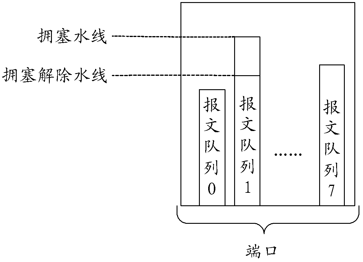
[0032] figure 2 A schematic diagram of the cache usage of the port. During the communication process of the message processing device, it is detected whether congestion occurs by detecting the buffer usage of the destination port. Such as figure 2 As shown, at least one message queue is included in the cache of a port, and different message queues transmit messages with different processing priorities. In an existing packet processing device, each port generally includes 8 packet queues, which respectively transmit 8 packets with different processing priorities. see figure 2 , the eight message queues are respectively marked as message queue 0, message queue 1 to message queue 7. Each message queue has its own buffer waterline. Taking message queue 1 as an example, figure 2 Shows the congestion waterline and congestion relief waterline of the message queue 1. When the current buffer waterline of message queue 1 is greater than or equal to the congestion waterline, i...


PUM


Abstract

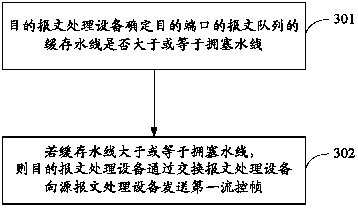
The invention provides a congestion control method and a message processing device. The congestion control method comprises the steps of determining whether the buffer water line of a message queue of a destination port is larger or equal to a congestion line, wherein the messages in the message queue have the same processing priority; and if the buffer water line is larger or equal to the congestion line, sending a first flow control frame to a source message processing device by exchanging the message processing device, wherein the first flow control frame comprises an MAC (media access control) address of the destination port and indicating information that the message queue is in a congestion state, so that the message corresponding to the message queue can be discarded by the source message processing device. With the adoption of the congestion control method and the message processing device, the use ratio of system bandwidth resources of the internet of a switch can be improved.

Description

technical field [0001] The invention relates to communication technology, in particular to a congestion control method and message processing equipment. Background technique [0002] In a Layer 2 switch network, there are application scenarios for transmitting packets across packet processing devices. figure 1 It is a structural schematic diagram of an existing switch network. exist figure 1 In , the packet processing device is specifically a chip as an example. Such as figure 1 As shown, the first chip and the third chip are connected through the second chip, the first chip is used as the source message processing device, the second chip is used as the exchange message processing device, the third chip is used as the destination message processing device, and the message is sent from The source port input of the first chip is transmitted to the third chip after passing through the first chip and the second chip, and the third chip outputs the message from its own destin...

Claims


Application Information

Patent Timeline
Patent Type & Authority Applications(China)
IPC IPC(8): H04L12/56H04L47/20
Inventor 许书亮
Owner RUIJIE NETWORKS CO LTD
Learn More