Oil-water separation device for leakage drainage system in hydropower station

A technology for oil-water separation device and drainage system, applied in liquid separation, separation methods, chemical instruments and methods, etc., can solve the problems of increasing the maintenance workload of the power station and reducing the reliability of the system, and achieves strong capabilities, reliable work, and high capacity. big effect

Active Publication Date: 2014-03-12
CHINA WATER RESOURCES BEIFANG INVESTIGATION DESIGN & RES
View PDF9 Cites 0 Cited by
  • Summary
  • Abstract
  • Description
  • Claims
  • Application Information

AI Technical Summary

Problems solved by technology

The filter element needs to be cleaned regularly, and it needs to be replaced when it reaches the service life or is clogged to a certain extent, which increases the maintenance workload of the power station and reduces the reliability of the system

Method used


Image

  • Oil-water separation device for leakage drainage system in hydropower station
  • Oil-water separation device for leakage drainage system in hydropower station

Examples


Embodiment Construction

[0015] Below in conjunction with accompanying drawing and specific embodiment the present invention is described in further detail:

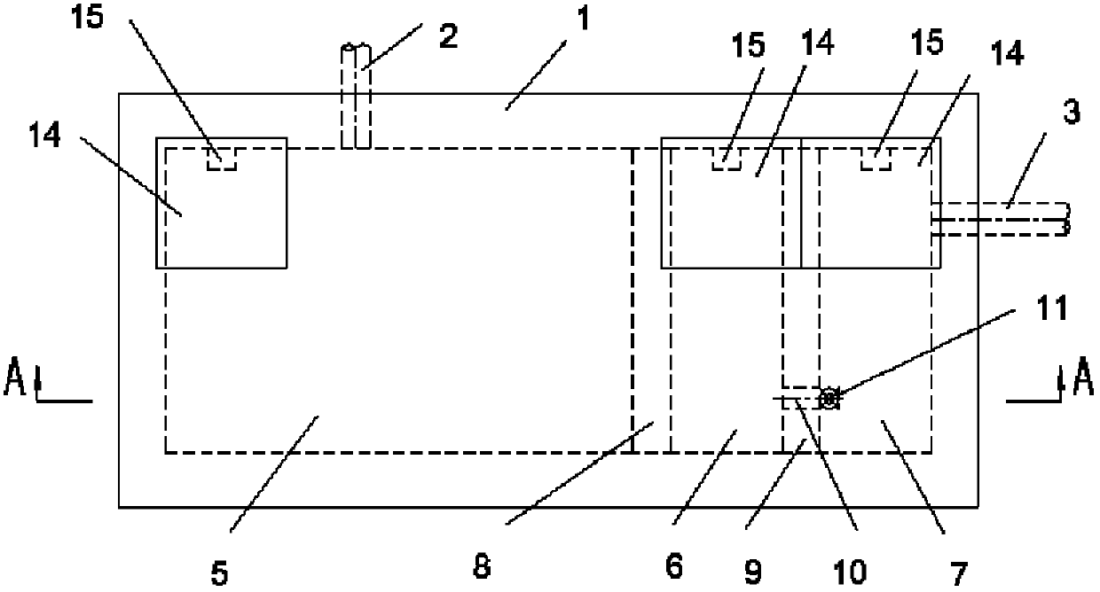
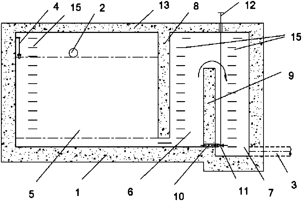
[0016] Such as figure 1 , 2 As shown, the oil-water separation device for the seepage and drainage system of a hydropower station of the present invention includes a pool 1, an oily sewage inlet pipe 2, a drain pipe 3 and a float alarm switch 4, and the inner space of the pool 1 is vertically partitioned by a first partition 8 The oil-water separation tank 5, the buffer tank 6 and the drain tank 7 which are connected to each other by the vertical second partition 9 are successively divided into the bottom of the oil-water separation tank 5 and the buffer tank 6 which are divided by the first partition 8, and are separated by the second partition 9 The divided buffer tank 6 is connected to the top of the drain tank 7; the oily water inlet pipe 2 is located at the upper part of the oil-water separation tank 5 and is higher than the top of the sec...


PUM


Abstract

The invention discloses an oil-water separation device for a leakage drainage system in a hydropower station, which comprises a water pool, an oily water inlet pipe, a water discharging pipe and a floating ball alarm switch. The inner space of the water pool is sequentially divided into an oil-water separation groove, a cushion groove and a water discharging groove which are communicated internally by an upright first partition and a second partition, the oil-water separation groove divided by the first partition is communicated with the bottom part of the cushion groove, and the cushion groove divided by the second partition is communicated with the top part of the water discharging groove; the oily water inlet pipe is arranged in the upper part of the oil-water separation groove and is higher than the top end of the first partition, the water discharging pipe is arranged in the lower part of the water discharging groove, and the floating ball alarm switch is arranged in the oil-water separation groove. The device provided by the invention has strong oil separation capability and large capacity, totally relies on gravity without other machines or electric separation equipment in separation, has reliable working performance, and is free of maintenance, simple and practical.

Description

technical field [0001] The invention relates to an oil-water separation device, in particular to an oil-water separation device used in a seepage drainage system of a hydropower station. Background technique [0002] At present, most of the oil-water separation measures adopted in the drainage system of hydropower stations use a kind of mechanical and electrical equipment-oil-water separation device. [0003] The existing oil-water separation device is assembled into a whole by housing, primary filter, fine filter, electric plunger pump, screw pump, electric heater and various valves. The device uses a sewage pump to suck oily sewage, and then enters the primary filter. The oil droplets in the water float up to the oil collection chamber of the device after polymerization, and most of the oil is separated. After the primary filter, the water still contains tiny oil particles, and these sewage containing tiny oil particles are discharged into the fine filter chamber for coar...

Claims


Application Information

Patent Timeline
Patent Type & Authority Patents(China)
IPC IPC(8): B01D17/028
Inventor 杨富超李力伟董克青闫国福刘婕马韧韬杨旭
Owner CHINA WATER RESOURCES BEIFANG INVESTIGATION DESIGN & RES
Why Eureka
Try Eureka