Thin film ink catalyst
A technology of catalysts and catalyst membranes, applied in catalyst activation/preparation, physical/chemical process catalysts, organic compound/hydride/coordination complex catalysts, etc.
- Summary
- Abstract
- Description
- Claims
- Application Information
AI Technical Summary
Problems solved by technology
Method used
Image
Examples
example 1
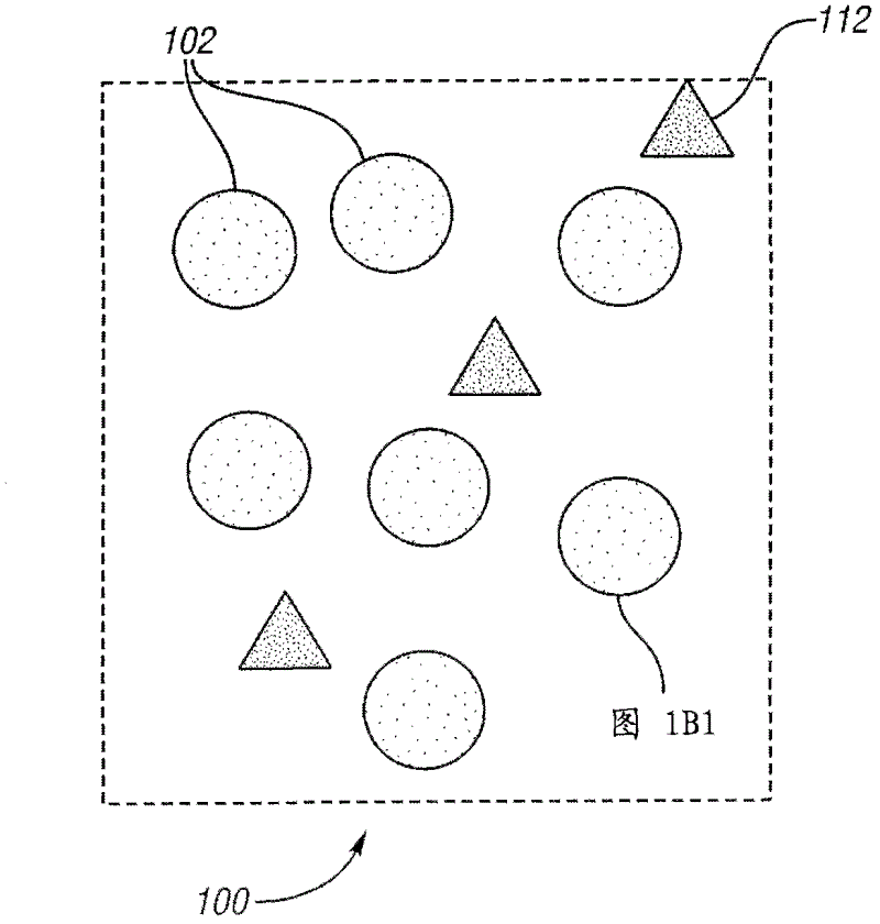
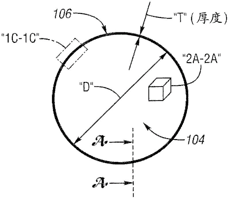
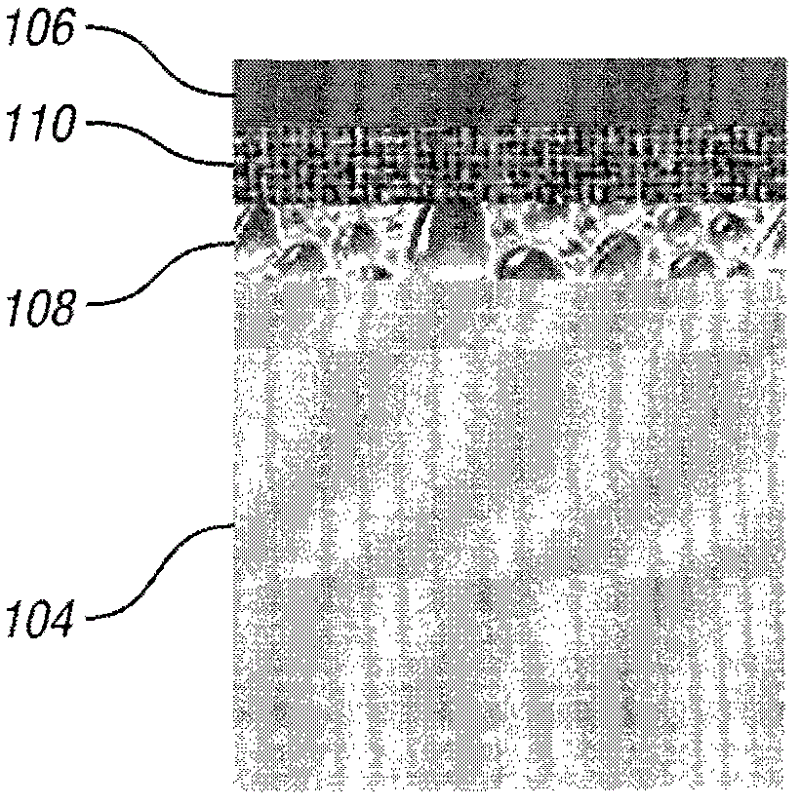
[0054] Glass spherical particles with a diameter of 3 μm were coated with 4 atomic layers of Pt catalyst. The thickness of the catalyst layer was 20 micrometers. The dense packing limit for spheres is about 0.74 or 74%. It is to be noted that the dense packing limit is 74% and the void volume is 26% for the face centered cubic aligned spheres. Packing limits can vary with particle shape. In order to include other ingredients in the paint, the glass spheres constitute approximately 34% of the volume of the catalyst paint layer, with the remaining total volume filled with other ingredients such as porous carbon and ionomer. The calculated values shown in Table 1 show an expected surface area increase of 13.6 cm 2 / cm 2 , while the Pt loading was much reduced to 3.3×10 -5 g / cm 2 or 0.033mg / cm 2 .
[0055] Table 1
[0056] Density of Glass Particles
example 2
[0058]Glass spherical particles with a diameter of 1 μm were coated with 4 atomic layers of Pt catalyst. The thickness of the catalyst coating layer was 20 micrometers. The dense packing limit for spheres is about 0.74 or 74%. In order to include other ingredients in the coating, the glass spheres constitute approximately 45% of the volume of the catalyst coating layer, with the remainder of the total catalyst volume filled with other ingredients such as porous carbon and ionomer. The calculated values shown in Table 2 show a desired surface area increase of 54 cm 2 / cm 2 , while the Pt loading is much reduced to about 1.3×10 -4 g / cm 2 or 0.13mg / cm 2 .
[0059] Table 2
[0060] Density of Glass Particles
example 3
[0062] Spherical glass particles with a diameter of 75 microns were obtained from Sigma Aldrich. Using atomic layer deposition (ALD) techniques in Figure 4A with Figure 4B A Pt layer of approximately 33 nm was deposited on the surface of the sphere depicted in .
[0063] An example catalyst coating consists of 100 mg of Pt-coated glass spheres to which 100 mg of 20 wt% Ion Power Nafion solution and 400 mg of 99% Acrylic acid for dry loading of 17 wt% Nafion are added. Triols. Stir the paint at 180rpm in a glass bottle for 6 to 8 hours. Most of the Pt-coated glass beads settled to the bottom of the bottle. If the coating solution was left unstirred overnight, the dispersed beads settled (the prepared coating was not dense enough to support a stable suspension of Pt-coated glass beads). The coating solution was applied to ETEK LT2500-wGDL (353 μm) with a cotton-tipped applicator to cover the GDL surface. The coated GDL was dried at 80°C for 2 hours and vacuum dried at 80...
PUM
| Property | Measurement | Unit |
|---|---|---|
| size | aaaaa | aaaaa |
| thickness | aaaaa | aaaaa |
| surface area | aaaaa | aaaaa |
Abstract
Description
Claims
Application Information
 - R&D
- Intellectual Property
- Life Sciences
- Materials
- Tech Scout
- Unparalleled Data Quality
- Higher Quality Content
- 60% Fewer Hallucinations
Browse by: Latest US Patents, China's latest patents, Technical Efficacy Thesaurus, Application Domain, Technology Topic, Popular Technical Reports.
© 2025 PatSnap. All rights reserved.Legal|Privacy policy|Modern Slavery Act Transparency Statement|Sitemap|About US| Contact US: help@patsnap.com


