Method for automatically determining measurement time in detection of energy spectrometer

A technology of measuring time and automatic determination, which is applied in the direction of material analysis using measurement of secondary emissions, can solve the problems of wasting measurement time, insufficient measurement time, affecting measurement efficiency, etc., and achieves the goal of increasing accuracy, improving efficiency, and avoiding interference. Effect

Active Publication Date: 2012-08-01
湖北方圆环保科技有限公司
View PDF7 Cites 6 Cited by
  • Summary
  • Abstract
  • Description
  • Claims
  • Application Information

AI Technical Summary

Problems solved by technology

However, if the measurement time is too long, on the one hand, it will seriously affect the detection efficiency of the sample, and at the same time, it will also be affected by factors such as ambient temperature and instrument stability, thus affecting the measurement results.
[0003] In the current blind test, the selection of the measurement time often depends on the experience of the spectrometer user, which will increase the uncertainty of the measurement results
[0004] The measurement time required for samples with different activities is also different. Compared with samples with high activity, samples with low activity often require longer measurement sampling time in the measurement. However, due to the unknown activity of the sample in the blind test , experimenters tend to take as long as possible to sample, which will waste unnecessary measurement time and affect the detection efficiency of the sample. At the same time, it will also increase the probability of adverse factors such as environmental changes being introduced into the measurement results
Moreover, if it is found that the measurement time is not enough when the sample measurement is completed, the sample will generally be required to be re-measured, which will further affect the measurement efficiency.

Method used


Image

  • Method for automatically determining measurement time in detection of energy spectrometer
  • Method for automatically determining measurement time in detection of energy spectrometer
  • Method for automatically determining measurement time in detection of energy spectrometer

Examples


Embodiment Construction

[0036] The embodiments of the present invention will be further described below in conjunction with the drawings.

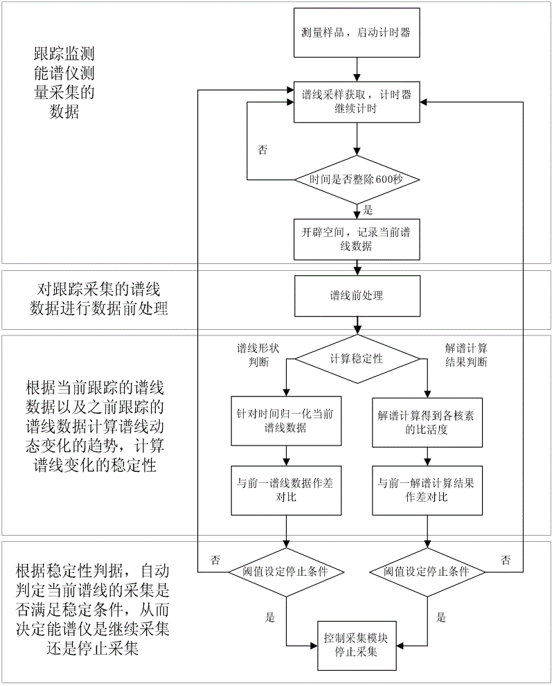
[0037] Such as figure 1 As shown, the present invention sequentially includes the following steps:

[0038] A: Track and monitor the measured sample in real time. The spectrum data collected by the energy spectrometer will be buffered;

[0039] B: Perform data pre-processing on the traced and buffered spectral line data in step A;

[0040] C: Obtain stability parameters according to the currently tracked spectral line data and the spectral line data processed in step B;

[0041] D: Perform stability judgment and automatically determine whether the current spectrum collection meets the stable conditions; if the conditions are met, the measurement collection of the samples is automatically stopped, if the conditions are not met, continue to measure and sample and track the spectrum data.

[0042] Among them, the energy spectrometer acquisition module is used to collect the sp...


PUM


Abstract

The invention discloses a method for automatically determining measurement time in the detection of an energy spectrometer. The method is characterized by comprising the following steps of: (1) tracking and monitoring data collected by the energy spectrometer in real time for a sample to be measured and caching the data; (2) carrying out data pretreatment on the spectral line data tracked and cached in the step (1); (3) acquiring a stability parameter according to the spectral line data tracked currently and the spectral line data treated in the step (2); (4) carrying out stability judgment, automatically judging whether the collection of a current spectral line meets a stability condition or not; and automatically stopping the measurement sampling of the sample if the condition is met, otherwise continuing the measurement sampling and tracking the spectral line data if the condition is not met. By using the method, the measurement time can be automatically determined in the process that the sample is measured by the energy spectrometer; the measurement efficiency of the sample is effectively improved; the influence of environmental change on a measurement result is effectively reduced; and meanwhile, the uncertainty of the measurement time judged manually is reduced.

Description

Technical field [0001] The invention relates to a method for automatically determining the measurement time in the detection of an energy spectrometer. Background technique [0002] High-energy particle detection energy spectrometers, such as NaI spectrometers, have been widely used in building materials radioactivity detection and soil radioactivity detection, and have become one of the test and measurement equipment required by the national standard. The NaI spectrometer generally uses a thick lead chamber as a shield, and the NaI scintillation crystal coupled with a photomultiplier tube constitutes a gamma-ray detector to detect and discriminate the high-energy photons emitted by the sample under test. Since the NaI energy spectrometer has good environmental radiation shielding conditions, and the NaI scintillation crystal has higher detection efficiency and better energy resolution, the NaI detector can perform more accurate measurements on samples with low activity (in sampl...

Claims


Application Information

Patent Timeline
IPC IPC(8): G01N23/22
Inventor 张博张晶秦家宝
Owner 湖北方圆环保科技有限公司
Why Eureka
Try Eureka