Optical projection system for improving stray light near projection picture

A technology of optical projection and stray light, applied in optical projection. field, it can solve the problems that the brightness of the stray light image cannot reach the acceptable range, and the reflection cannot be completely eliminated, so as to achieve the effect of compact structure, elimination of interference, and improvement of quality

Inactive Publication Date: 2012-08-01
FUJIAN NETCOM TECH
View PDF7 Cites 24 Cited by
  • Summary
  • Abstract
  • Description
  • Claims
  • Application Information

AI Technical Summary

Problems solved by technology

[0005] In order to solve the trouble caused by the stray light area 60, there are many ways, combining figure 2 , one of which is to add a frame line plane light-blocking element 61 before the digital micromirror device 50 to block stray light from entering the effective area of ​​the digital micromirror device 50. The light-blocking surface is a black plane, but there are still some stray light reflections, The reflected stray light enters the imaging lens 70 and is projected around the effective projection area 80, which only slightly darkens the images outside the effective image area 80, and the brightness of the stray light image cannot reach the acceptable range
The other is to add a frame row of plane light-blocking elements before the digital micromirror device, and reduce the reflection of stray light by increasing the roughness of the light-blocking surface, but it cannot completely eliminate the reflection, and only allows images outside the effective image area 80 It just gets darker, and the brightness of the stray light image is still not within the acceptable range

Method used


Image

  • Optical projection system for improving stray light near projection picture
  • Optical projection system for improving stray light near projection picture
  • Optical projection system for improving stray light near projection picture

Examples


Embodiment Construction

[0023] In order to describe the technical content, structural features, achieved goals and effects of the present invention in detail, the following will be described in detail in conjunction with the embodiments and accompanying drawings.

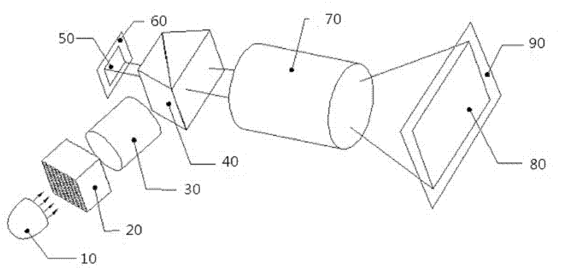
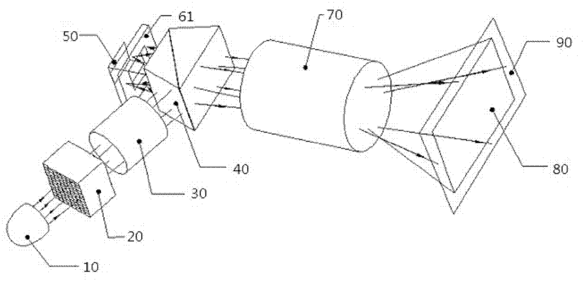
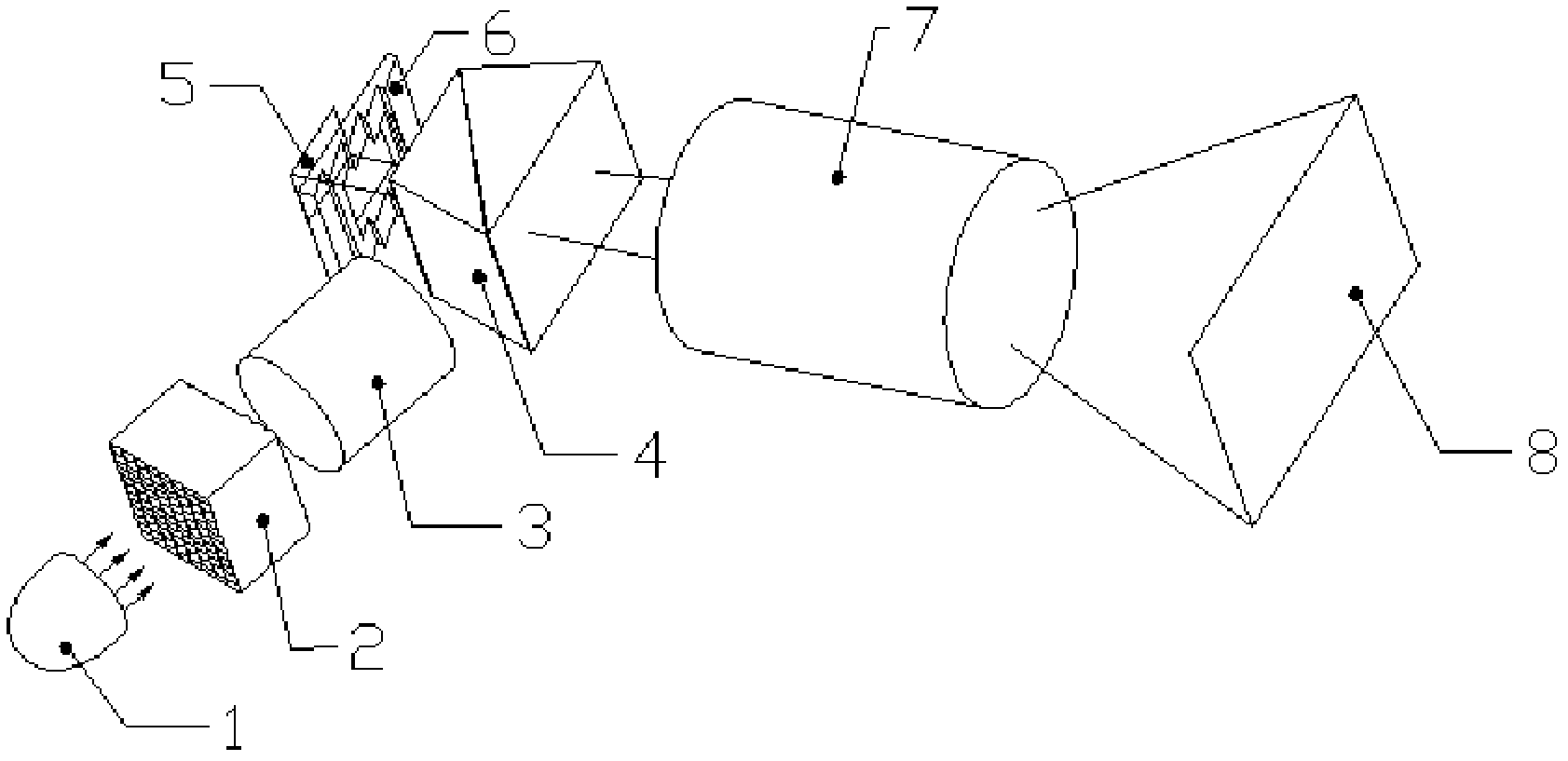
[0024] The present invention provides an optical projection system for improving stray light near the projection screen, comprising a light source illumination subsystem, a TIR prism 4, a digital micromirror device 5 and an optical imaging subsystem arranged in sequence; the TIR prism is arranged on the digital micromirror Between the mirror device and the optical imaging subsystem; the light source lighting subsystem includes a light source 1, a fly eye lens 2 and a relay lens group 3 arranged in sequence; the optical imaging subsystem includes an imaging lens 7 and a screen arranged in sequence; The relay lens group 3 is arranged between the fly eye lens 2 and the TIR prism 4, and the imaging lens 7 is arranged between the TIR prism 4 and...


PUM


Abstract

The invention discloses an optical projection system for improving stray light near a projection picture. The optical projection system comprises a light source illumination subsystem, a total indicated runout (TIR) prism, a digital micro-mirror device and an optical imaging subsystem, which are sequentially arranged; the optical imaging subsystem comprises an imaging lens and a screen, which are sequentially arranged; the light source is used for emitting a light beam; a fly-eye lens is used for receiving the light beam emitted by the light source and for homogenizing the light beam; a relay lens unit is used for transferring the light beam which is homogenized by the fly-eye lens to the TIR prism; the received light beam is projected onto the digital micro-mirror device after being totally reflected by the TIR prism; the digital micro-mirror device modulates the received light beam and reflects the light beam to be projected onto the imaging lens through the TRI prism; the light beam is imaged on the screen through the imaging lens; and the optical projection system also comprises a light blocking element for preventing the stray light from entering the digital micro-mirror device, and the light blocking element is arranged on an incidence light path of the digital micro-mirror device; and a light blocking surface of the light blocking element is in a zigzag structure.

Description

technical field [0001] The invention relates to an optical system for a projector, in particular to an optical projection for improving stray light near a projection screen. Background technique [0002] With the development of computer multimedia display technology, projectors, as the best large-screen display equipment, have gradually become standard computer peripheral products and are widely used in various fields such as education, military, and business. During the use of the projector, users often require the projected image to have high quality and contrast. Therefore, it is necessary to improve the stray light of the projector optical system to improve the projector image quality and contrast. [0003] Generally, a projector using a digital micromirror device (DMD, digital micromirror device) works on the principle that the digital micromirror device has a plurality of micromirrors as optical switches, receives electronic signals, and changes the inclination of the ...

Claims


Application Information

Patent Timeline
Patent Type & Authority Applications(China)
IPC IPC(8): G02B27/18G02B26/08G02B27/09G02B5/02G03B21/28
Inventor 张嵘
Owner FUJIAN NETCOM TECH
Why Eureka
Try Eureka