Synchronous transmission system of energy and information

A technology of synchronous transmission and energy information, which is applied in the field of synchronous transmission system of energy and information, can solve the problems of high cost, large volume, and adding signal modulators, and achieve the effect of stable amplitude, small volume, and centralized control

Active Publication Date: 2013-12-11
ZHEJIANG UNIV
View PDF1 Cites 0 Cited by
  • Summary
  • Abstract
  • Description
  • Claims
  • Application Information

AI Technical Summary

Problems solved by technology

However, the realization of power line carrier communication often requires an additional carrier modulation circuit, which includes a coupling transformer, which is large in size and high in cost; at the same time, traditional power line carrier communication is to superimpose digital signals on existing power lines for communication. The energy of the channel is not controlled, and the characteristics of the channel cannot be changed
[0006] The Chinese patent application number 200910191716.3 discloses an energy signal synchronous transmission device and method. This technology adds a signal modulator to the main circuit and a signal extraction and recovery circuit to the secondary circuit. It is the same as the power line carrier communication. An additional signal modulator needs to be added, which increases the size and cost of the circuit, and is only used to adjust the injected energy of the system

Method used


Image

  • Synchronous transmission system of energy and information
  • Synchronous transmission system of energy and information
  • Synchronous transmission system of energy and information

Examples


Embodiment Construction

[0029] In order to describe the present invention more specifically, the technical solutions of the present invention will be described in detail below in conjunction with the accompanying drawings and specific embodiments.

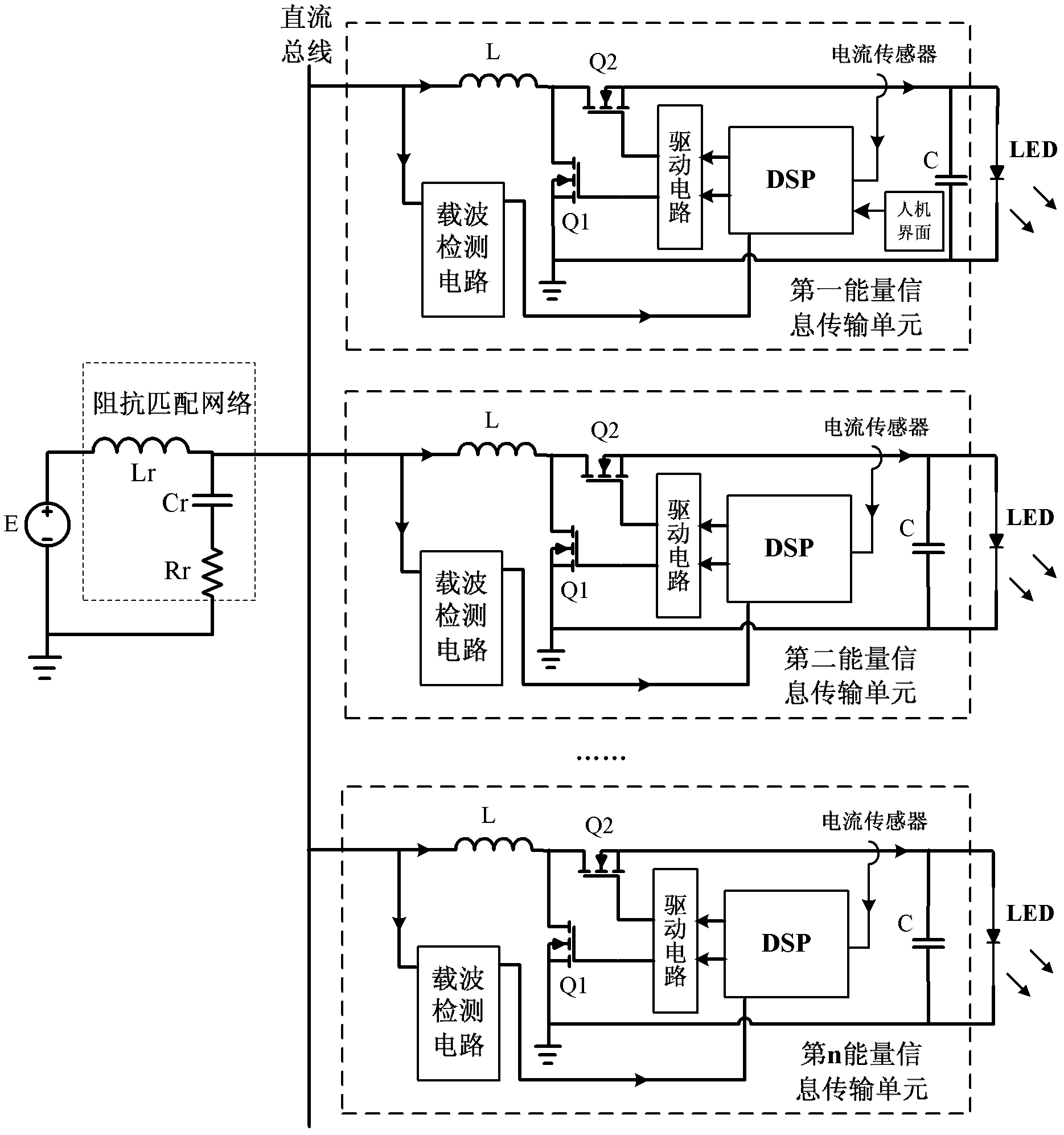
[0030] Apply the present invention in LED lighting system, such as figure 1 As shown, a synchronous transmission system of energy and information includes: a DC power supply E, a DC bus and n energy information transmission units connected to corresponding loads; n energy information transmission units are all connected to the DC bus; the present The load in the embodiment is an LED (Light Emitting Diode).

[0031] The DC power supply E is connected to the DC bus through an impedance matching network; the impedance matching network includes an inductor Lr, a capacitor Cr and a resistor Rr; wherein, one end of the inductor Lr is connected to the positive pole of the DC power supply E, and the other end is connected to one end of the capacitor Cr The other...


PUM


Abstract

The invention discloses a synchronous transmission system of energy and information, which comprises a direct current bus, a direct current power supply and a plurality of energy information transmission units, and the direct current power supply and the plurality of energy information transmission units are connected with the direct current bus. Each energy information transmission unit comprises a Boost circuit, a sampling circuit, a carrier detecting circuit, a control circuit and a driving circuit. The synchronous transmission system of the energy and the information enables power line carrier communication technology to be combined with characteristics of the Boost circuits, achieves synchronous transmission of the energy and the information under the premise that circuit modulation is not required additionally, volume of the system and use of corresponding devices are reduced, extra connecting lines are not required, and characteristics of communication channels can be designed according to requirements.

Description

technical field [0001] The invention belongs to the technical field of power electronic communication, and in particular relates to a synchronous transmission system of energy and information. Background technique [0002] With the rapid development of electronic technology, new concepts such as the Internet of Things are gradually being accepted by people. Whether it is a different power conversion system or a different power conversion module in the same system, in order to achieve the intended function, in addition to the need for the power supply to provide electric energy, it also requires the cooperation and coordination of the communication function between each other. [0003] In power electronics technology, the DC-DC (direct current-direct current) converter originally only realizes the conversion and transmission of energy by controlling the opening and closing of the switching tube. When a system has multiple DC-DC converters powering different devices, it is of...

Claims


Application Information

Patent Timeline
Patent Type & Authority Patents(China)
IPC IPC(8): H04B3/54
Inventor 杜进吴建德何湘宁
Owner ZHEJIANG UNIV
Why Eureka
Try Eureka