Supercharge Your Innovation With Domain-Expert AI Agents!

High-speed multifunctional ball electric spindle

A multi-functional, electro-spindle technology, used in clamping, supporting, positioning devices, etc., can solve the problems of reducing the temperature of the spindle, single function, affecting the force of the tie rod, etc., to meet the requirements of high-precision machining, accurate tool position, ensure The effect of safe use

Active Publication Date: 2012-08-08
GUANGZHOU HAOZHI ELECTROMECHANICAL
View PDF5 Cites 14 Cited by
  • Summary
  • Abstract
  • Description
  • Claims
  • Application Information

AI Technical Summary

Problems solved by technology

[0002] In the prior art, the body of the ball electric spindle is mainly used to fix and install bearings, bearing housings, stators and other components, but as the shell of the spindle, it often cannot protect the normal operation of each component, especially for high-speed ball spindles. No circulating cooling system can be provided to reduce the temperature of the spindle when it is working
The aluminum water jacket assembly for the ball high-speed electric spindle has a complex structure, which is not conducive to the heat dissipation of the spindle, inconvenient installation, single function, and difficult to grasp the assembly accuracy
The air cylinder in the pneumatic tool unloading mechanism for the ball high-speed electric spindle has a complex structure, low sealing performance, and unstable transmission. Frequent tool changes are easy to damage or leak air.
The bearing seat assembly for the ball high-speed electric spindle has a single structure, difficult processing, inconvenient loading and unloading, and difficult to adjust the axial stability. After assembly, it will also affect the force of the pull rod, pull claw, etc., and the function of pulling and unloading the knife cannot be realized, and the service life is short, requiring frequent replacement. Therefore, the speed of the current ball electric spindle is not high, and the service life is not long.

Method used


Image

  • High-speed multifunctional ball electric spindle
  • High-speed multifunctional ball electric spindle
  • High-speed multifunctional ball electric spindle

Examples


Embodiment 1

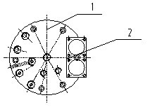
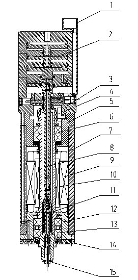
[0041] like Figure 1 to Figure 13 As shown in each figure, the present invention has a cylinder assembly (2), the top side of the cylinder assembly (2) cylinder top cover (2.1) is provided with a wire groove (1), and the piston of the cylinder assembly (2) is pushed out. The rod assembly (8), the bottom of the cylinder assembly (2) is fixed with an aluminum water jacket assembly (3), the inner through hole of the aluminum water jacket assembly (3) is provided with an encoder (4), and the bottom of the aluminum water jacket assembly (3) is fixed There is an upper bearing seat (5), and an upper bearing assembly (6) is arranged inside the upper bearing seat (5), the organic body assembly (7) is fixed at the bottom of the upper bearing seat (5), and the motor stator (9) is arranged inside the body assembly (7). ), the shaft core assembly (10) is provided at the axial through hole of the motor stator (9), and the shaft core assembly (11) is provided in the through hole in the midd...

Embodiment 2

[0043] Same as Example 1, except that the cylinder top cover (2.1), cylinder block (2.3), and the bottom of the cylinder block (2.3) are fixed on the top of the aluminum water jacket (2.7), and the cylinder body protrusion (2.6) is embedded in aluminum In the groove on the top of the water jacket (2.7), a sealing ring is provided at the edge and inner wall contact between the cylinder body (2.3) and the aluminum water jacket (2.7). The first-stage piston (2.2), the middle part of the inner chamber of the cylinder block (2.3) directly below the first-stage piston (2.2) is provided with the second-stage piston (2.4), and the inner chamber of the cylinder block (2.3) directly below the second-stage piston (2.4) The lower part is provided with a three-stage piston (2.5), and seal rings are provided at the contact points between the first-stage, two-stage and three-stage pistons and the inner chambers of the cylinders at all levels.

Embodiment 3

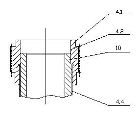
[0045] Same as Example 1, except that the inner cavity of the main body of the aluminum water jacket (3.1) is provided with an inner cavity seat through which the shaft of the push rod (3.5) penetrates, and the inner side of the inner cavity seat is radially provided with a release knife Proximity switch (3.3), the interior of the inner cavity seat is also radially provided with a broach proximity switch (3.6); the outer wall of the main body of the aluminum water jacket where the loose knife proximity switch (3.3) and the broach proximity switch (3.6) are located It is blocked by a cross-recessed plug assembly (3.4); the loosening knife proximity switch (3.3) and the broaching knife proximity switch (3.6) are fixed in the inner cavity seat by an axial set screw (3.2).


PUM


Abstract

The invention relates to a high-speed multifunctional ball electric spindle, in particular to a high-speed electric spindle for machining machine tool balls, which comprises an aluminum jacket assembly, a motor stator, a spindle core assembly and the like. Working revolution number of the high-speed multifunctional ball electric spindle can reach 40000rpm. The high-speed multifunctional ball electric spindle is high in accuracy, large in torsion, long in service life and convenient for popularization and application.

Description

technical field [0001] The invention relates to a machining equipment, in particular to a high-speed electric spindle for machining machine tool balls. Background technique [0002] In the prior art, the body of the ball electric spindle is mainly used to fix and install bearings, bearing housings, stators and other components, but as the shell of the spindle, it often cannot protect the normal operation of each component, especially for high-speed ball spindles. A circulating cooling system cannot be provided to reduce the temperature of the spindle when it is working. The aluminum water jacket assembly for the ball high-speed electric spindle has a complex structure, which is not conducive to the heat dissipation of the spindle, inconvenient installation, single function, and difficult to grasp the assembly accuracy. The air cylinder in the pneumatic tool unloading mechanism for the ball high-speed electric spindle has a complex structure, low sealing performance, and...

Claims


Application Information

Patent Timeline
IPC IPC(8): B23B19/02B23Q17/00B23Q11/12B23Q3/155
Inventor 汤秀清
Owner GUANGZHOU HAOZHI ELECTROMECHANICAL
Features
  • R&D
  • Intellectual Property
  • Life Sciences
  • Materials
  • Tech Scout
  • Unparalleled Data Quality
  • Higher Quality Content
  • 60% Fewer Hallucinations
Learn More