Axial electromagnet bearing

An electromagnetic bearing and axial technology, which is applied in the direction of shafts and bearings, bearings, mechanical equipment, etc., can solve the problems of low utilization rate of permanent magnets and insufficient axial size, and achieve compact structure, small axial size, and high current The effect of high stiffness

Inactive Publication Date: 2012-08-08
刘延风
View PDF7 Cites 7 Cited by
  • Summary
  • Abstract
  • Description
  • Claims
  • Application Information

AI Technical Summary

Problems solved by technology

For example, the Chinese patent 200710135188.0 permanent magnet bias axial radial magnetic bearing is a relatively compact hybrid electromagnetic bearing, sharing a pair of bias permanent magnets, but its axial size is not small enough
200510011272.2 A low-power permanent magnet bias axial magnetic bearing. An excitation air gap is set on the side of the bias permanent magnet. It is also a magnetic short-circuit channel for the bias permanent magnet, resulting in a low utilization rate of the permanent magnet. The characteristic is that all magnetic poles are Participate in work that produces execution

Method used


Image

  • Axial electromagnet bearing
  • Axial electromagnet bearing
  • Axial electromagnet bearing

Examples


Embodiment Construction

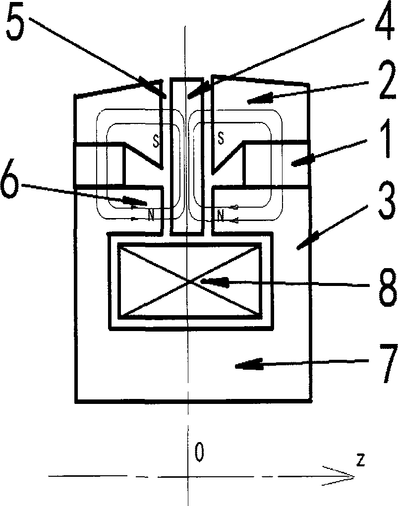
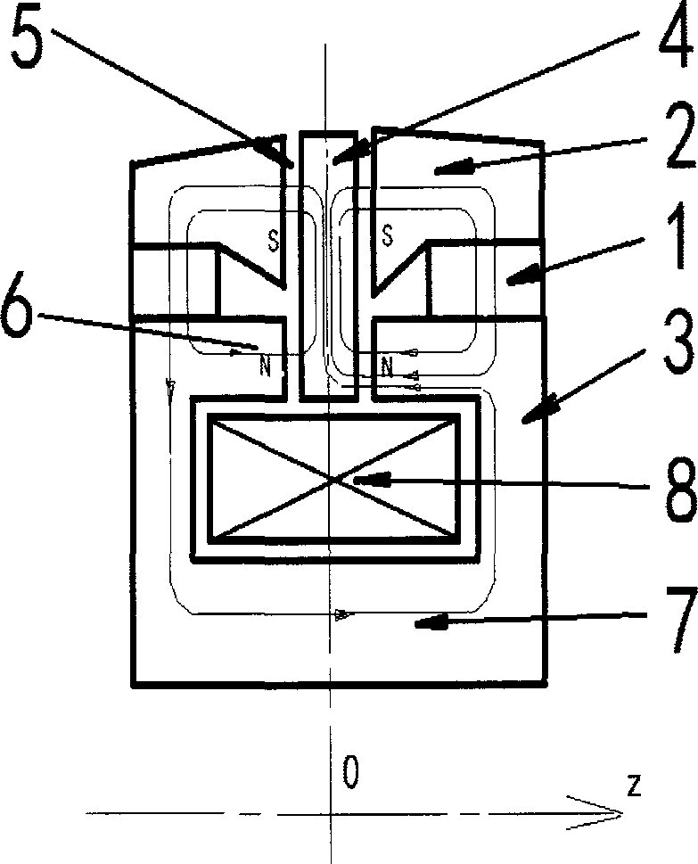
[0025] figure 1 It is a schematic diagram of the magnetic force lines of the permanent magnet bias flux along the magnetic circuit. The polarity of the magnetic poles on both sides is axisymmetric to the center line of both sides, and the S poles are all outside according to the radial direction. The two sides of the bias flux magnetic field line respectively pass through the high magnetic flux density small magnetic pole 6, the air gap 5, the rotor suction cup 4, the air gap 5, the low magnetic flux density large magnetic pole 2, and the bias permanent magnet 1 to form a loop, the low magnetic flux density is large The magnetic pole 2 has a large area so the magnetic flux density is low. The volume of the bias permanent magnet 1 on one side is larger than that on the other side, that is, the magnetic force of the air gap 5 on one side is greater than that on the other side. When the rotor is erected, the rotor sucker 4 has a suction difference at the balance position to bala...


PUM


Abstract

The invention discloses a permanent magnet polarization axial electromagnet bearing, which is compact in structure, simple in manufacture process, large in executive force contribution and high in electricity efficiency. The axial electromagnet bearing is provided with a polarization permanent magnet (1), stator cores (3), a rotor sucking disc (4) and a gap (5). A high magnetic flux density small pole (6) and a low magnetic flux density big pole (2) are both arranged on the stator cores (3) on two sides of the rotor sucking disc (4), polar area ratio is smaller than and equal to 0.5, the polarization permanent magnet (1) is absorbed between the high magnetic flux density small pole (6) and the low magnetic flux density big pole (2), polarity of the high magnetic flux density small pole (6) on the two sides is same, the high magnetic flux density small poles (6) axially face to the rotor sucking disc (4) and are linked through a winding iron core (7), and a concentrated winding (8) is located in a radial space of the rotor sucking disc (4) and located in a cavity of winding iron core (7). The axial electromagnet bearing of the structure is small in volume, particularly the axial dimension is small enough, support of an axis-free outer rotor is effective, manufacture is simple, force contribution is big, the permanent magnet is safe and lose no magnetism, magnetism stiffness is big, reliability is strong, and efficiency is high.

Description

technical field [0001] The invention relates to an electromagnetic force suspension bearing, in particular to an axially active electromagnetic bearing with external control current permanent magnetic bias, which is used for non-contact magnetic force support of rotors or non-rotating parts. Background technique [0002] Magnetic bearings are generally divided into two categories: active and passive. Active refers to the type that inputs electric energy from the outside and generates control force. For example, 200510011272.2 is a low-power permanent magnet bias axial magnetic bearing, which is the mainstream of magnetic bearings; The control force is achieved by the conversion of the motion energy of the loaded parts, such as superconducting magnetic bearings, dynamic damping bearings such as US patent US6304015 magneto-dynamic bearings and permanent magnetic repulsion bearings. According to Enshaw's theorem, the entire suspension stabilization system cannot be constructed ...

Claims


Application Information

Patent Timeline
Patent Type & Authority Applications(China)
IPC IPC(8): F16C32/04
CPCF16C32/0476F16C32/0465
Inventor 刘延风
Owner 刘延风
Why Eureka
Try Eureka