Supercharge Your Innovation With Domain-Expert AI Agents!

Optical fiber temperature sensor

An optical fiber temperature and sensor technology, used in thermometers, thermograms, thermometer components, etc., can solve the problem of inability to directly use optical fiber temperature monitoring devices, and achieve the effects of excellent insulation, easy exchange, and rust prevention.

Active Publication Date: 2012-08-08
TOSHIBA MITSUBISHI-ELECTRIC IND SYST CORP +1
View PDF6 Cites 1 Cited by
  • Summary
  • Abstract
  • Description
  • Claims
  • Application Information

AI Technical Summary

Problems solved by technology

Therefore, tunnel disaster prevention equipment can be applied to large-scale structural parts, or large-scale linear structures represented by tunnels, but it is impossible to directly use optical fiber temperature monitoring devices in the extremely narrow space inside the machine

Method used


Image

  • Optical fiber temperature sensor
  • Optical fiber temperature sensor
  • Optical fiber temperature sensor

Examples


Embodiment 1

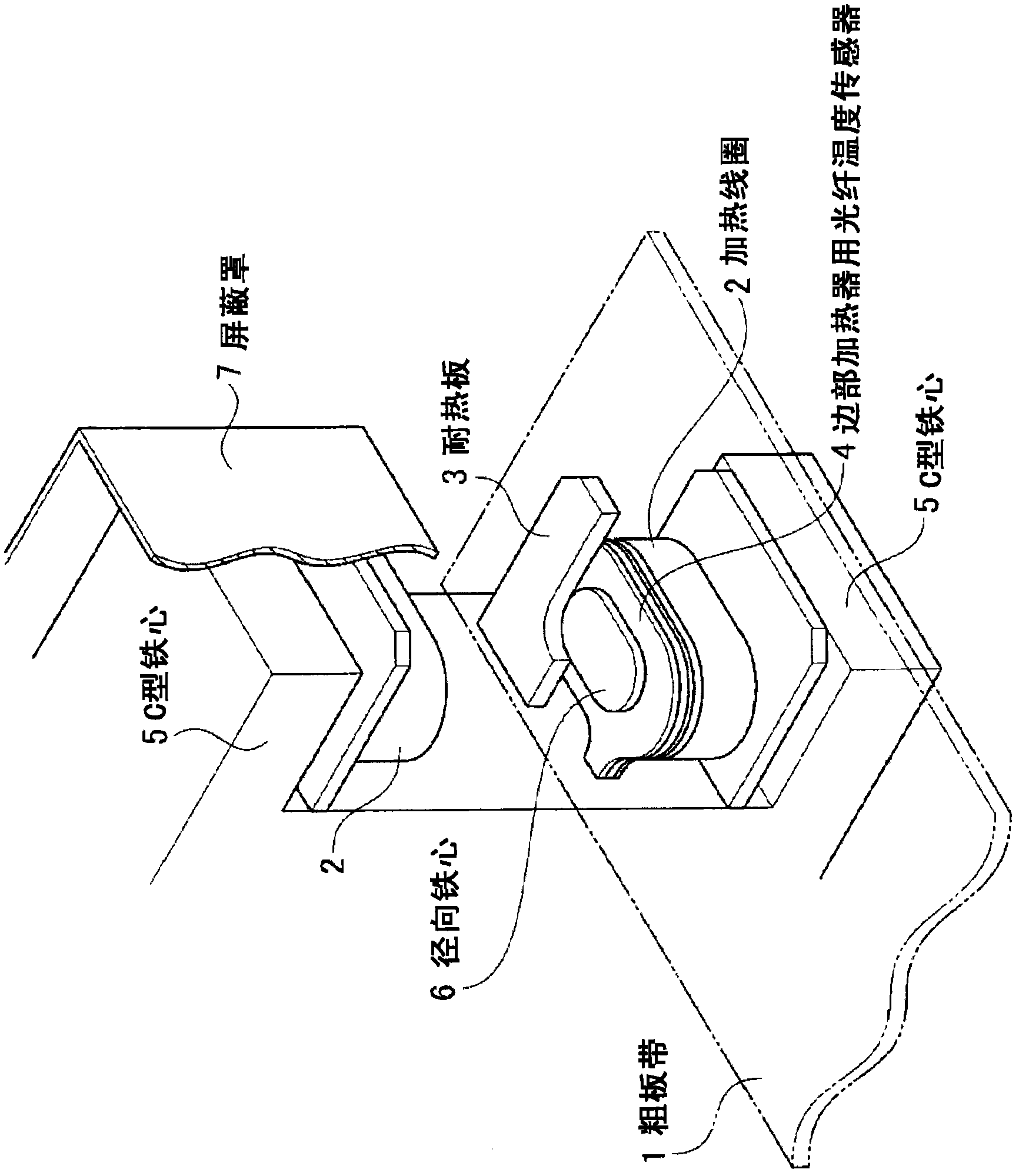
[0052] figure 1 It is a perspective view showing an edge heater provided with an optical fiber temperature sensor according to Embodiment 1 of the present invention. exist figure 1 Among them, on the lower surface of the rough plate strip 1 formed by the plate material, the heating coil 2 and the heat-resistant plate 3 are arranged oppositely, and between the heating coil 2 and the heat-resistant plate 3, an elliptical side heating plate is arranged. The fiber optic temperature sensor 4 is used for the device.

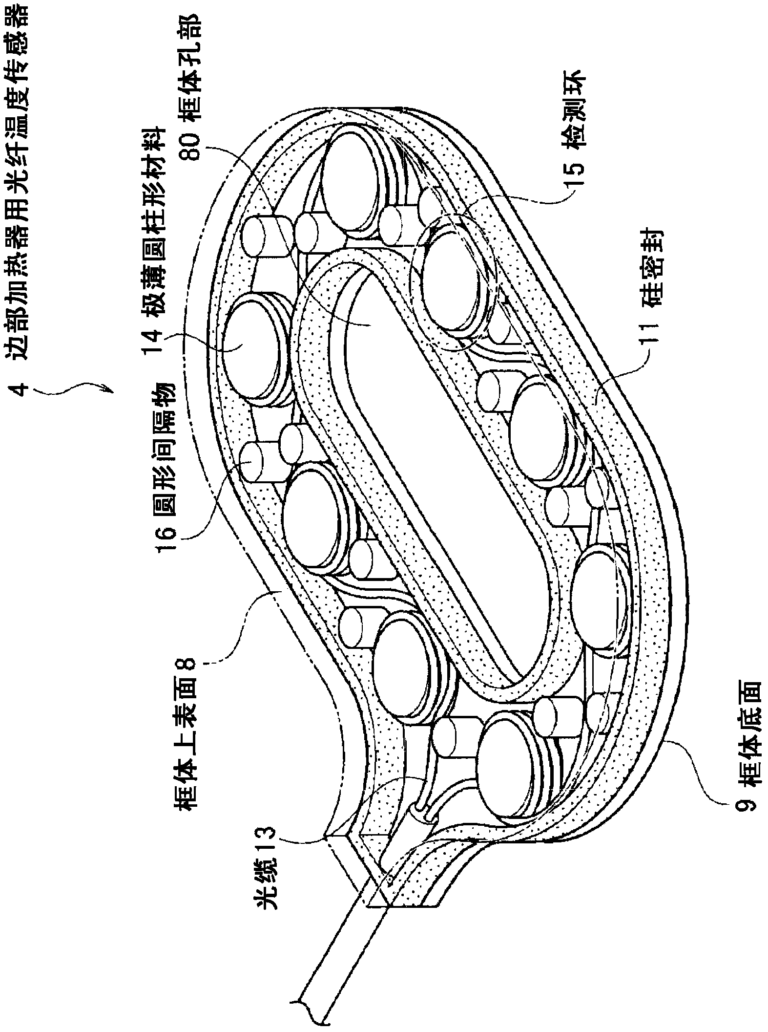
[0053] Such as figure 2 As shown, on the edge heater optical fiber temperature sensor 4, a frame body hole 80 is formed, and a figure 1The elliptical radial core 6 is shown. The heating coil 2 , the heat-resistant plate 3 , and the optical fiber temperature sensor 4 are arranged below the recess of the C-shaped core 5 . In addition, heating coil 2 , heat-resistant plate 3 (not shown), and optical fiber temperature sensor 4 (not shown) are also arranged above the ...

Embodiment 2

[0068] Figure 5 (a) is a perspective view showing a strip heater provided with an optical fiber temperature sensor according to Example 2 of the present invention. Figure 5 (b) is a cross-sectional view showing an optical fiber temperature sensor according to Example 2 of the present invention.

[0069] exist Figure 5 In the shown example 2, four flat-shaped optical fiber temperature sensors 4a to 4d are sequentially arranged on the inner lower surface side of the box-shaped heating coil 2a along the longitudinal direction of the heating coil 2a. On the upper surfaces of the optical fiber temperature sensors 4a to 4d, a heat-resistant plate 3a covering the rough strip 1 is arranged.

[0070] The shape of the optical fiber temperature sensors 4 a to 4 d for strip heaters is preferably flat. The reason is that the strip heater is formed by a wound heating coil 2a, and its surface opposite to the rough strip 1 is in a planar shape, and the strip heater optical fiber tempera...


PUM

PropertyMeasurementUnit
Thicknessaaaaaaaaaa

Abstract

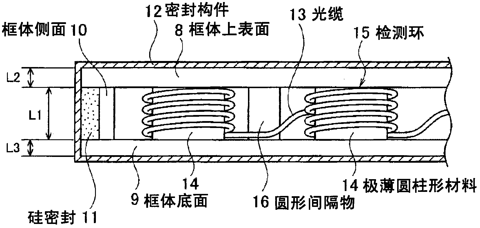
The invention provides an optical fiber temperature sensor which can keep on monitoring the temperatures of an expected position in an induction heating apparatus for steel hot rolling lines. A cable (13) is accepted in a frame (8,9) formed by extremely thin sheets which are made of electrical insulating material same with the materials forming the induction heating apparatus to form the optical fiber temperature sensor. A plurality of extremely thin cylindrical materials (14) formed by the materials same with the frame materials are accepted in a plurality places in the frame; the cable (13) is winded to have a length more than a length equivalent to distance resolution and is not fixedly winded on each material of the plurality of extremely thin cylindrical materials (14) so as to form a plurality of detection rings (15) which are utilized to detect temperatures of a plurality of places.

Description

technical field [0001] The present invention relates to an optical fiber temperature sensor for constantly monitoring the temperature inside an induction heating device used in a hot rolling line for iron and steel. Background technique [0002] In a hot rolling line for iron and steel, a heating furnace preliminarily heats a material to be heated (rolled material) to a rolling temperature, and a rough rolling mill forms the material to be heated into a state called a rough strip. In addition, the finishing mill forms the rough strip into a thin plate having a desired thickness and width. In such a hot rolling line for iron and steel, an induction heating device is used for the purpose of heating and soaking the rough strip while reducing the temperature of the rough strip during wire transportation, and reducing the load on the rolling mill. [0003] As such an induction heating device, an edge heater for raising the temperature of both edge portions of a rough strip and a...

Claims


Application Information

Patent Timeline
IPC IPC(8): G01K11/32G01K1/08B21B38/00
CPCG01J3/0218G01K1/028G01K1/045G01K1/08G01K11/32G01K2213/00H05B6/10
Inventor 桥本英二堂上康治小幡健志
Owner TOSHIBA MITSUBISHI-ELECTRIC IND SYST CORP
Features
  • R&D
  • Intellectual Property
  • Life Sciences
  • Materials
  • Tech Scout
  • Unparalleled Data Quality
  • Higher Quality Content
  • 60% Fewer Hallucinations
Learn More