
Shift register, array substrate driving circuit and display apparatus

A shift register and drive control technology, applied in static memory, digital memory information, instruments, etc., can solve problems such as inability to ensure the power of capacitor C1, display interference, and affect picture quality, and achieve the effect of improving picture display quality

Inactive Publication Date: 2012-08-08
BEIJING BOE OPTOELECTRONCIS TECH CO LTD
View PDF2 Cites 12 Cited by
  • Summary
  • Abstract
  • Description
  • Claims
  • Application Information

AI Technical Summary

Problems solved by technology

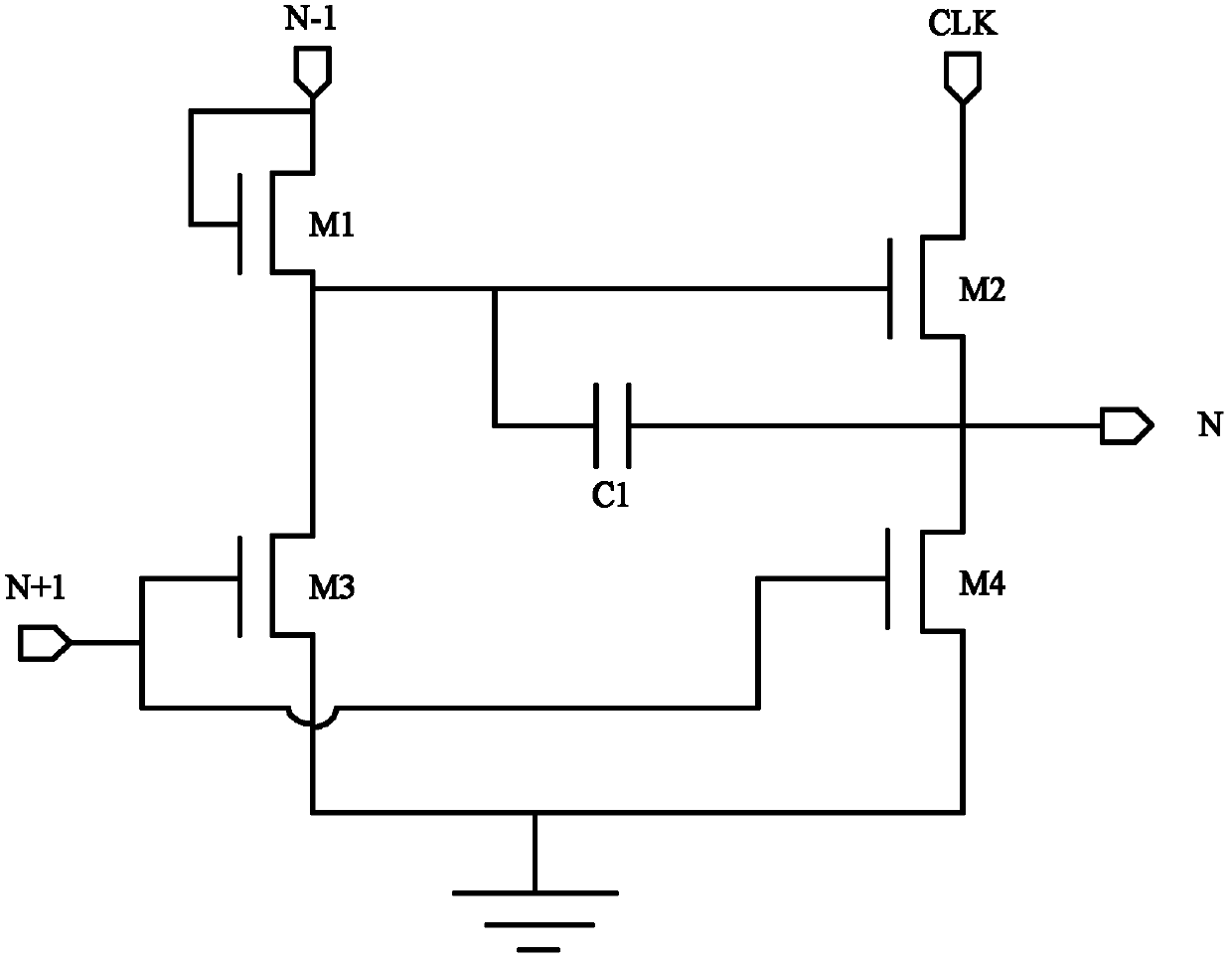
[0013] Since the time to discharge the capacitor C1 is only the N+1th cycle, the capacitor C1 cannot be discharged later. Since the time of one cycle is short, it cannot ensure that the power of the capacitor C1 is completely discharged. Therefore, the capacitor C1 is in Subsequent cycles may also generate a driving voltage to the second thin film transistor M2, so that the second thin film transistor M2 is turned on, and when the CLK signal is at a high level, the output terminal of the second thin film transistor M2 is at a high level, but this time The period is the non-working period of the GoA circuit, therefore, the output signal of the second thin film transistor M2 will interfere with the display of the entire picture, affecting the picture quality

Method used


Image

  • Shift register, array substrate driving circuit and display apparatus
  • Shift register, array substrate driving circuit and display apparatus
  • Shift register, array substrate driving circuit and display apparatus

Examples


Embodiment Construction

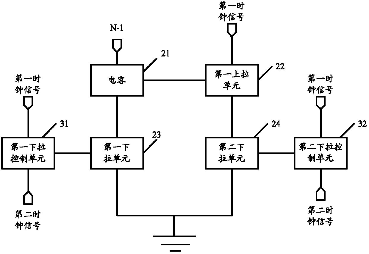
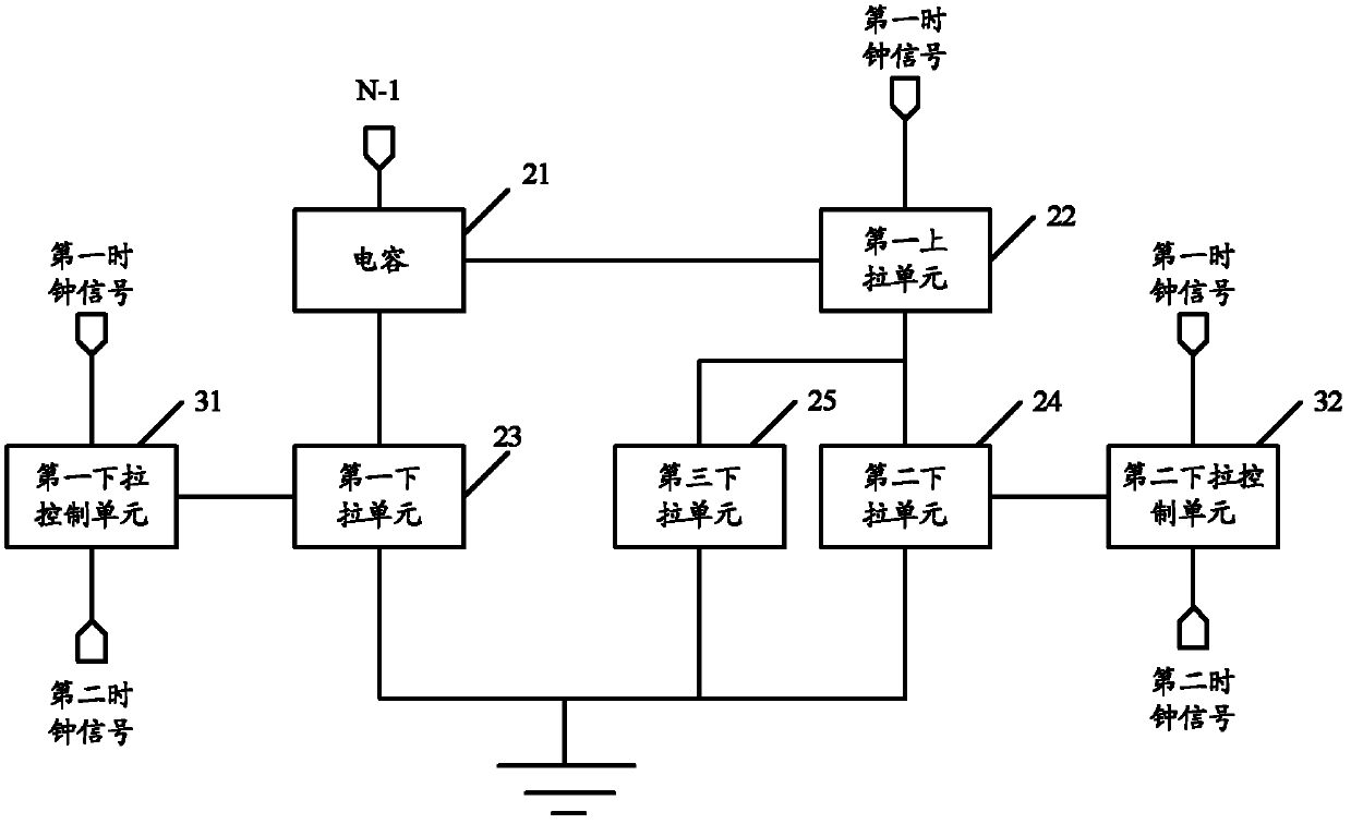
[0061] The embodiment of the present invention provides a shift register, which can periodically discharge the capacitor and the output terminal in the non-working area, so as to ensure that the output signal of the shift register is zero when the shift register is in the non-working area, and will not affect the display of the entire screen. Generate interference and improve picture display quality. The shift register includes: a capacitor, which receives the trigger signal output by the output terminal of the upper shift register, and charges under the control of the trigger signal to provide the first drive control voltage to the first pull-up unit; the first pull-up unit , connected to the first clock signal output terminal, used to perform switching operation under the control of the first drive control voltage, thereby controlling the output of the first clock signal from the signal output terminal; the first pull-down control unit, in the first Under the control of the ...


PUM


Abstract

The invention discloses a shift register, an array substrate driving circuit and a display apparatus so as to realize that the shift register can carry out periodic discharging on a capacitor and an output terminal in a non-working region and ensure that a signal output by the shift register in the non-working region is zero and interference to whole frame display is not generated. The shift register comprises the capacitor, a first pull-up unit, a first drop-down unit, a first drop-down control unit, a second drop-down unit and a second drop-down control unit, wherein the capacitor is charged under the control of a triggering signal so as to provide a first driving control voltage; the first pull-up unit makes a first clock signal output under the control of the first driving control voltage; the first drop-down unit periodically carries out discharging on the capacitor; the first drop-down control unit makes the first drop-down control unit periodically carry out discharging on the capacitor under the control of the first clock signal and a second clock signal; the second drop-down unit periodically carries out discharging on the output terminal of the first pull-up unit; the second drop-down control unit makes the second drop-down unit carry out discharging on the output terminal of the first pull-up unit under the control of the first clock signal and the second clock signal.

Description

technical field [0001] The invention relates to the field of liquid crystal display, in particular to a shift register, an array basic driving circuit and a display device. Background technique [0002] At present, TFT (Thin Film Transistor, Thin Film Field Effect Transistor) is used to set up the GoA circuit; the characteristic of TFT is that the threshold voltage is affected by its gate voltage, the higher the duty cycle, the higher the threshold voltage rises, and the weaker the current driving capability. [0003] Such as figure 1 Shown is a circuit structure diagram of a mobile register in the prior art, including a first thin film transistor M1, a second thin film transistor M2, a third thin film transistor M3, a fourth thin film transistor M4 and a capacitor C1, wherein: [0004] Both the source and the gate of the first thin film transistor M1 are connected to the output terminal N-1 of the upper GoA unit, and the drain is respectively connected to the gate of the s...

Claims


Application Information

Patent Timeline
Patent Type & Authority Applications(China)
IPC IPC(8): G09G3/36
CPCG09G3/36G11C19/28G09G3/3677G09G2310/0286
Inventor 崔文海
Owner BEIJING BOE OPTOELECTRONCIS TECH CO LTD
Learn More