Gasification furnace and chilling chamber thereof

A chilling chamber and gasifier technology, which is applied in the gasification of granular/powdered fuels, the manufacture of combustible gas, and the petroleum industry. It can solve problems such as fluctuations in the liquid level of the chilling chamber, fluctuations, and increased chilling water supply flow. , to achieve the effect of reducing the content of fine solid particles, increasing the washing area, and inhibiting the phenomenon of water.

Active Publication Date: 2012-08-15
CHNA ENERGY INVESTMENT CORP LTD +1
View PDF6 Cites 8 Cited by
  • Summary
  • Abstract
  • Description
  • Claims
  • Application Information

AI Technical Summary

Problems solved by technology

[0010] In addition, when the production load is relatively high, since the annular gap between the riser and the downcomer is relatively narrow, the flow rate of the syngas after leaving the water bath is fast, which is easy to cause the phenomenon of syngas carrying liquid, even if the syngas in the quenching chamber leaves There is a separation baffle in the channel, and the high-speed flowing gas still sweeps away the small liquid droplets on the baffle to carry liquid again. The liquid in the quenching chamber will easily cause the liquid level in the quenching chamber to drop rapidly and cause the gasifier to trip. It is necessary to increase the chilled water supply flow to ensure the liquid level, which not only increases the energy consumption and waste of water resources, but also increases the load of the rear system at once, which affects the stable operation; when the operating temperature of the gasifier is high , resulting in a high heat load

Method used


Image

  • Gasification furnace and chilling chamber thereof
  • Gasification furnace and chilling chamber thereof
  • Gasification furnace and chilling chamber thereof

Examples


Embodiment Construction

[0046] The embodiments of the present invention will be described in detail below with reference to the accompanying drawings, but the present invention can be implemented in many different ways defined and covered by the claims.

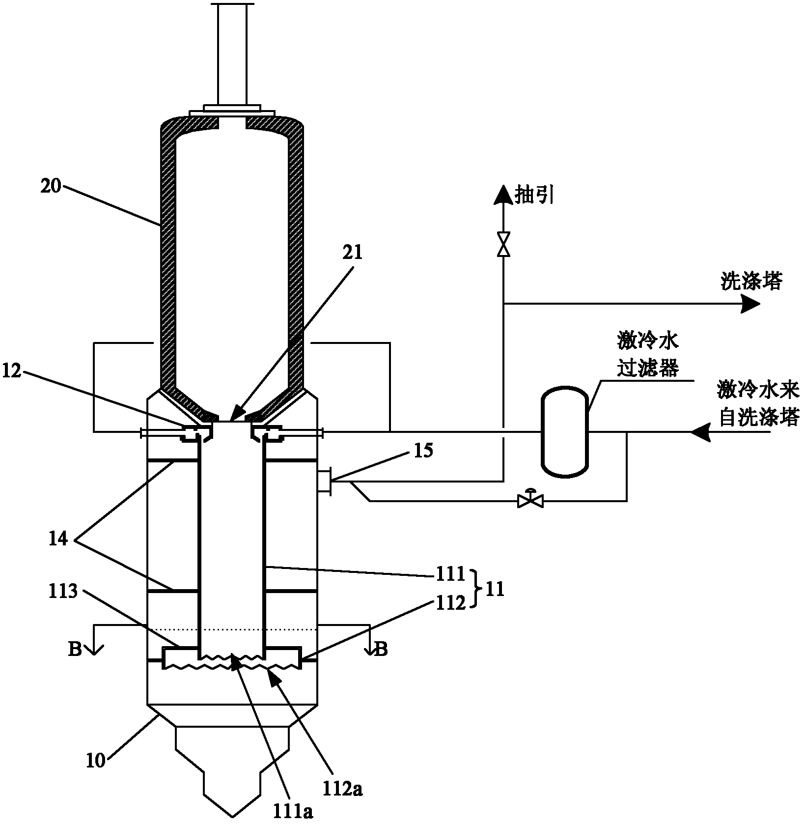
[0047] figure 1 and figure 2 A schematic structure of a fluidized gasifier according to a first embodiment of the present invention is shown. Such as figure 1 and figure 2 As shown, the gasification furnace includes a combustion chamber 20 and a quench chamber 10 located below the combustion chamber. The high-temperature syngas and molten slag in the combustion chamber 20 enter the downcomer 11 through the slag port 21 at the bottom.

[0048]In this embodiment, the double-sleeve structure of the concentric and coaxial ascending pipe and descending pipe of the prior art is not adopted, and only the descending pipe is reserved. The sleeve structure of the connected part is fixedly connected with the inner wall of the quenching chamber by the sup...


PUM


Abstract

The invention discloses a gasification furnace and a chilling chamber of the gasification furnace of the gasification furnace. The chilling chamber of the gasification furnace comprises a downcomer consisting of a gas reduction tube and a gas distribution tube, wherein the lower end of the gas reduction tube extends into the gas distribution tube, a gas exhausting net is arranged in a circular space between the gas distribution tube and the gas reduction tube, the lower edge of the gas reduction tube is lower than the plane where the gas exhausting net is positioned, and a plane where the gas exhausting net is positioned is lower than the liquid level of the chilling chamber. Compared with the prior art, for the gasification furnace provided by the invention, an ascending pipe is removed, the water-bringing phenomenon of the synthesis gas of the chilling chamber is effectively inhibited, and the water bath humidifying, dedusting, desmutting and temperature reduction effects of the synthesis gas are improved.

Description

technical field [0001] The invention relates to the field of gasification of gasification coal, in particular to a gasification furnace and a chilling chamber thereof. Background technique [0002] Coal is an important energy source. For a long time, the use of coal has been accompanied by serious environmental pollution. In recent years, people have paid more and more attention to clean coal technology aimed at reducing pollution emissions and improving utilization efficiency; coal gasification technology, as one of the coal processing and conversion technologies, is considered to be one of the most efficient and clean clean coal technologies. [0003] Modern coal gasification technology, especially high-pressure, large-capacity entrained-bed gasification technology has been widely used in industry. In our country, many manufacturers have introduced and used modern entrained bed gasification technology. Modern entrained bed gasification technology is mainly divided into co...

Claims


Application Information

Patent Timeline
IPC IPC(8): C10J3/48C10J3/84
Inventor 王进胡先君余建良唐煜
Owner CHNA ENERGY INVESTMENT CORP LTD
Why Eureka
Try Eureka