

Low-grade thermally-driven Rankine power generation device with ejector
A low-grade heat and power generation device technology, applied in steam engine devices, machines/engines, mechanical equipment, etc., can solve the problems of low power generation efficiency and poor economy, and achieve high power generation efficiency, increased work, and stable operation.
- Summary
- Abstract
- Description
- Claims
- Application Information
AI Technical Summary
Problems solved by technology
Method used
Image


Examples
Embodiment 1
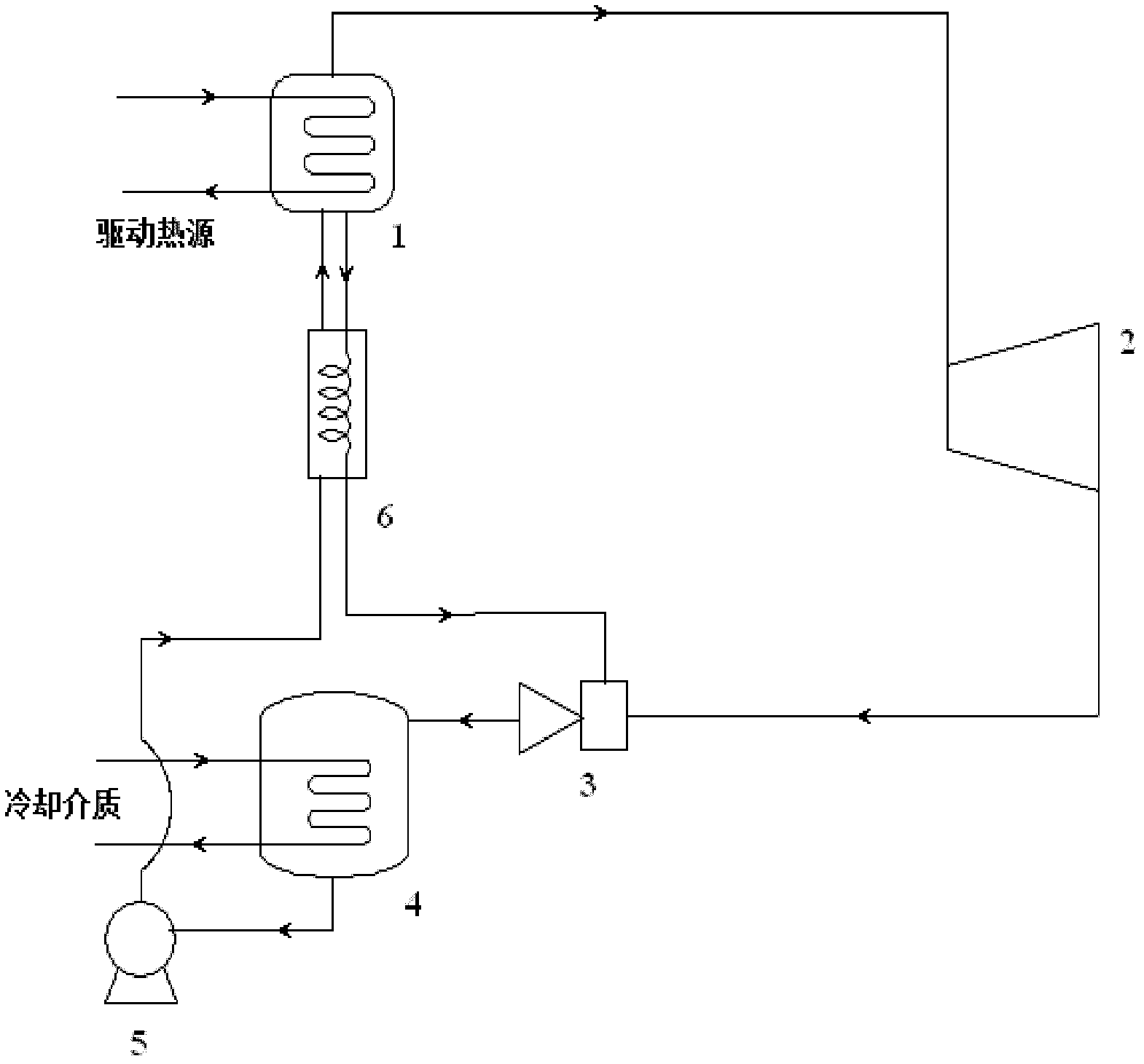
[0032] Such as figure 1As shown, a low-grade heat-driven Rankine power generation device with an injector in the present invention uses a mixture of carbon dioxide (R744 with a boiling point of -78.5°C under normal pressure) and acetone (with a boiling point of 56.5°C under normal pressure) as the working fluid. It is composed of generator 1, expander 2, generator (not shown in the figure), ejector 3, absorber 4, circulation pump 5 and solution heat exchanger 6, generator 1 is provided with generator steam outlet, generator solution The inlet, the outlet of the generator solution, and the inlet and outlet of the driving heat source communicated with the driving heat source. The ejector 3 is provided with an injection fluid inlet, a mixed liquid outlet and a working fluid inlet. The absorber 4 is provided with a cooling coil. The inlet and outlet of the tube are connected with the cooling medium source, and the cooling medium filled in the cooling coil is water.
[0033] The s...
Embodiment 2
[0037] A mixture of ammonia (boiling point of R717 at normal pressure is -33.5°C) and water (boiling point at normal pressure is 100°C) is used as the working fluid.
[0038] This embodiment uses low-grade heat at about 120°C, the heat conversion efficiency can be increased by about 20-30%, the mechanical work consumed by the circulation pump can be reduced by about 10-25%, and the net power generation efficiency of the device can be increased by about 25-55% at most .
Embodiment 3
[0040] Using a mixture of tetrafluoroethane (R134a with a boiling point of -26°C under normal pressure) and tetraglyme (DME with a boiling point of 275.3°C under normal pressure) as the working fluid, the structure of the power generation device, the connection methods of various components and Working process is identical with embodiment 1.
[0041] This embodiment utilizes low-grade heat at about 60°C, the heat conversion efficiency can be increased by about 20-35%, the mechanical work consumed by the circulation pump can be reduced by about 20-40%, and the net power generation efficiency of the device can be increased by about 30-70% at most .
PUM
| Property | Measurement | Unit |
|---|---|---|
| Boiling point | aaaaa | aaaaa |
| Boiling point | aaaaa | aaaaa |
| Boiling point | aaaaa | aaaaa |
Abstract
Description
Claims
Application Information